Model Elements
Walls
EDIT WALL IN PLACE
ARRANGE WALLS
STRETCH WALLS
APPROXIMATE WALL PATH
EDIT WALL IN PLACE
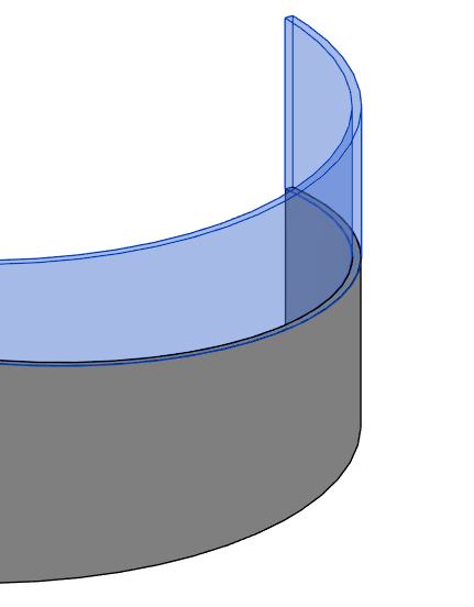
Freeform editing of the top or bottom face of walls.
*NOTE:
- you can edit one wall or a chain of walls, as long as they are connected, if you want a constant slope the walls must be tangent.
- Currently the tool does not work with slanted or tapered walls
- When editing wall, it may lead to deleting of some of annotations
- To achieve the desired results with curved or elliptical walls, Environment will create a Void element to cut the wall.
- Select the desired wall(s).
- Click Environment tab > Model Elements panel > Click on Edit Wall in Place.
Or - Click Environment tab > Model Elements panel > Click on Edit Wall in Place.
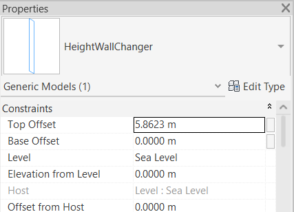
Once in the command, you will see the following options in the Options Bar:
- Check the Multiple check box to apply the edit to a chain of walls.
- Click Finish to complete your selection or Cancel to exit the command without changes.
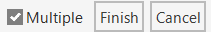
When in Editing Mode:
- Click anywhere along the editable wall to place the editing handles (you can place them at the edge or in the middle of the wall).
The EDIT WALL IN PLACE dialog box opens:
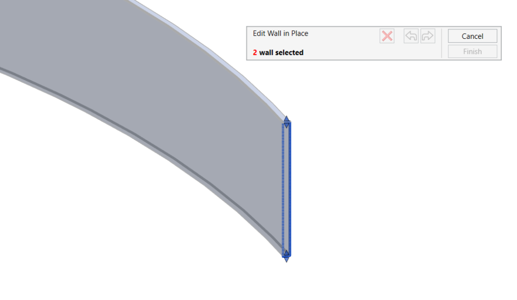
- You can manually drag the handles up and down to the desired height of the wall in the specified location.
Or - You can enter values to specify the height of the bottom and top parts of the wall.
- You can always use the Undo Redo
 buttons in the EDIT WALL IN PLACE dialog box
 - Click on the Delete
 button to remove the height of the selected handles (the handle will return to the original wall height and will not be deleted)
 - Click Finish to complete your editing or Cancel to exit the command without changes.
ARRANGE WALLS
Automatically create stepped walls that follow the slope of a surface by dividing a wall into segments that match the elevation of a reference surface.
*NOTE:
– This tool only works in 3D views.
– Only system family walls are supported.
– Slanted walls are not supported.
- Click on the Environment tab > Model Element panel > Arrange Walls
The ARRANGE WALLS dialog box opens:
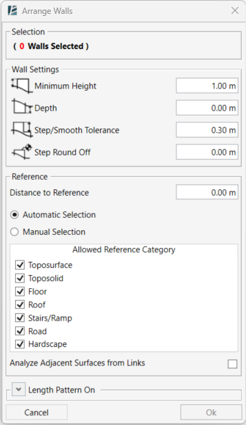
SELECTION
- Click on walls in your model to select.
- Press Tab to select a chain of connected walls.
- You can click and drag a selection window to select multiple walls at once.
- Click on a selected wall again to deselect it.
- The number of selected walls will be shown in red.
WALL SETTINGS
- Define a Minimum Height value for the wall segments measured from the surface.
- Define the Depth of the wall below the reference surface.
- Define Step/Smooth Tolerance, the vertical height difference between each wall step.
- Set Step Round Off to control the precision of top and base elevations.
Set to 0 to disable rounding.
REFERENCE
- Type the Distance to reference value, the horizontal distance from the wall where the reference elevation is sampled.
- Choose Automatic selection and specify the surface type by checking the relevant checkbox in the “Allowed Reference Category” list to let the tool find a suitable surface.
- Check the Analyze Adjacent Surfaces from Links checkbox to include linked models as potential reference surfaces.
or - Choose Manual selection and pick the reference surfaces, including linked surfaces, directly from your model space.
OPTIONAL: LENGTH PATTERN
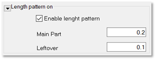
- Click the drop-down arrow “Length pattern” at the bottom of the dialog box to open the Length Pattern option.
- Check Enable length pattern to define a repeating sequence.
- Enter a value in the Main Part field to define the length of a repeated wall segment.
- Enter a value in the Leftover field to add additional length at the end of each sequence.
Set to 0 to disable.
*NOTE:
In most cases, after the length pattern is applied, a small portion of wall may still remain. This leftover length will be added to either the first or last segment of the sequence.
- Click OK to apply the tool and create stepped walls, or Cancel to exit without changes.
*NOTE:
You can re-select the wall at any time to test different design options or update parameters, no need to undo your last design change.
STRETCH WALLS
Change the top or base offset of multiple walls at once.
- Select several walls or a chain of walls
- Click environment tab > model element panel > the drop-down arrow next to the Arrange Walls command > Stretch Walls
The STRETCH WALLS dialog box opens:
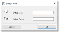
Define the base and top offset values
In the Stretch Wall dialog box:
- To add wall height, type a positive value in the Offset Top box.
- To subtract wall height, type a negative value in the Offset Top box.
For example, enter 0.5 to add wall height, or enter -0.5 to subtract wall height. - To deepen the wall base, type a negative value in the Offset Base box.
- To raise the wall base, enter a positive value in the Offset Base box.
For example, enter 0.5 to raise the wall base, or -0.5 to deepen the wall base. - Click Ok.
APPROXIMATE WALL PATH
Quickly turn any wall into a sequence of a few straight walls.
You can predefine the spacing and rotation of these wall segments

- Select the walls you would like to split > Click Environment tab > Model Element panel > Approximate Wall Path
The APPROXIMATE WALL PATH dialog box opens:
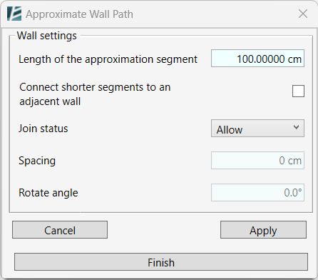
- Define the length of the segments to be created.
*NOTE:
Since Environment refers to the total length of the wall, after dividing the Walls into equal segments, you might have a leftover segment as mentioned before.
- Check the Connect Shorter Segments to an Adjacent Wall box if you want the leftover segment to be a part of the adjacent Wall segment.
- To allow spacing between the segments, change the join status to “Disallow”.
- Set the desired Spacing value to define the distance between the Wall segments. You can enter a negative or a positive value.
- Set the Rotate Angle value to rotate each of the segments at a predefined angle. The rotation axis point will be in the middle of each Wall segment.
*NOTE:
- At any point, you can click on Apply to review the changes without leaving the command. Continue editing the parameters and hit Apply until you reach the wanted result.
 - Once you click on Finish, you will not be able to go back to the command and edit the chain of walls
- Click on Finish to apply changes and exit the command.
Slabs
SHAPE BY TOPOGRAPHY
TERRACING SLOPE
COMPLETE SLAB
MATCH SLOPE
CURB RAMP
SHAPE BY TOPOGRAPHY
Draping slab’s sub-elements in alignment with a selected topography.
*NOTE:
- This command only works in 3D view.
- You can select the slabs and Toposurfaces before or after starting the command.
- Click on Environment tab > model element panel > Shape by Topography
The SHAPE BY TOPOGRAPHY dialog box opens:
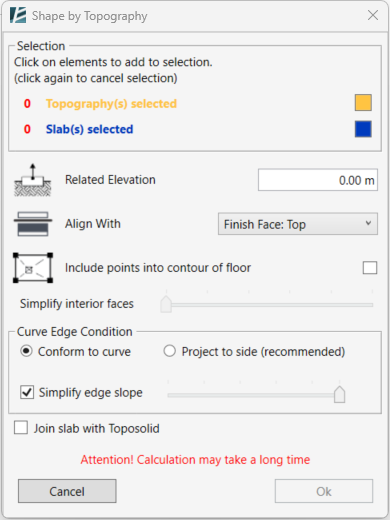
In the Shape by Topography dialog box:
- Select any slabs (Floors, Roofs or Toposolid) you wish to shape and the reference topographies (Toposurface or Toposolid) to shape them by.
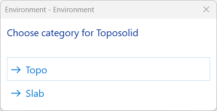
You can select as many surfaces and slabs as you wish as long as they overlap each other. Reference topographies can also be selected from a linked Revit model or linked Topographies from Civil 3D - In case you select a Toposolid, Environment will ask you if you would like to use it as a slab or a topography.
- In the model space, the elements will be highlighted in the corresponding color, and you will see the count of each element selected in the Selection panel of the window.
- You can change the highlighted colors by clicking the color box and selecting the preferred color.
- Type a Related Elevation value.
This determines the offset of the slab from the reference Toposurface. - Choose which layer of the Slab will be aligned with the Topography by selecting the Core or Finish layers from the drop-down menu next to Align With.
- Check the Include points into contour of floor box if you want to add points inside the slab boundary, or, uncheck this box to place elevation points on the slab boundary alone (recommended for narrow paths or roads).
- If you choose to add points to the boundary of the slab, you can use the Simplify interior faces slider to optimize and reduce the number of points transferred from the Topography into the slab. This might add some calculation time to the process, but will result in a lighter slab.
- You can select the desired Curve Edge Condition (Conform to curve or Project to side) similarly to how you would normally do it had you manually edit any slab. It is recommended to say with the default mode but if dealing with complex curves and the action fails, please try to change the curve edge condition.
- You can check the Simplify edge slope checkbox to optimize and reduce the number of points added to the boundary of the slab. Move the slider to set the level of simplification. We recommend that you start with the minimum smoothing. Moving the slider to the right decreases the number of added points but will also result in less accuracy.
- (Only on Revit 2024 and newer versions) You can check the Join Slab with Toposolid option to join the geometry of the selected elements.
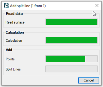
- Click Ok to start running the command.
- If the calculation takes too much time you can click on the Cancel button on the calculation window to stop the operation.
*NOTE:
If a curved floor does not align properly:
- Change the Curved Edge Condition
or
- Simplify the original topo-surface.
- Split the slab and try running the command a few times
- When working with Roof by Footprint, make sure no roof sketch line Defines Roof Slope.
TERRACING SLOPE
Create terraces that follow the slope of the selected surfaces.
*NOTE:
- If you are using Revit version 2021 or older, the resulting Floor will have an Opening element to define its shape. In newer Revit versions, the resulting Floor shape will be defined with the regular sketch boundary.
- This tool can be applied to Toposurfaces and Toposolids.
- To start, click on Environment tab > Model Elements > Terracing Slope (Found under the dropdown arrow of Shape by Topography)

The TERRACING SLOPE dialog box opens:
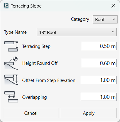
- In the ‘Category’ drop-down, choose the category you want to assign to your new terraces (Floors, Roofs, Ceilings*).
*Ceilings are only available in Revit 2022 and newer versions. - In the ‘Type Name’ drop-down, choose the type of Floor for the terrace you want to create.
- In the ‘Terracing Step’ box, enter a value to set the height of each terrace (riser).
- Enter your desired rounding value (including 0 for no rounding) in the ‘Height Round Off’ box. The rounding is referenced to the Internal Origin of your project.
- Use the ‘Offset From Step Elevation’ field to define the maximum gap between the terraces and the underlying selected surface.
- In the ‘Overlapping’ field, enter a value to define the amount of overlap between adjacent terraces (Use 0 for no overlap).
- Click on Apply to continue or Cancel to go back without changes.
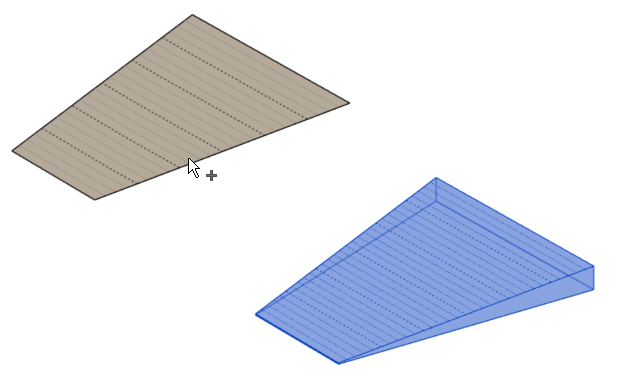
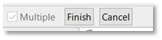
Once you click on Apply, you can select your sloped surface. Please notice that some options will appear in the Options Bar.
![]()
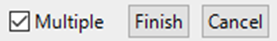
- Check the ‘Multiple’ option check box to select more than one surface.
- To create terraces, select the desired sloped surfaces by clicking on them once.
- To deselect a surface, click on it again.
- Once you select the surfaces, click ‘Finish’ to apply the command, or ‘Cancel’ to exit the command.
COMPLETE SLAB

Create a new slab (Floor or Roof) from an opening or hole in an existing slab. The hole can be created any way you choose; outlined by slab boundary, using an Opening element or cut with a Void element.
*NOTE:
- The new floor will be built at the selected level and will shape according to the original Slab’s slopes and elevations.
- This command doesn’t work with linked slabs (Floors or Roofs).
- Click Environment tab > Model Element panel > Click on Complete Slab.
- Select the designated slab.
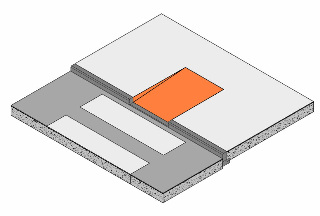
- Environment will then identify all the surface openings and will mark them with orange-colored shapes.
- Click to select the openings you wish to close and click finish.
The COMPLETE FLOOR dialog box opens:
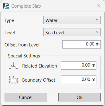
On the Complete Slab window:
- Select the slab Type to be used for the new slab created.
- Select the slab Level and Offset from Level.
- Define the Related Elevation (the distance from the reference slab).
- Enter a value in the Boundary Offset field to apply an offset or leave it at 0 for no offset.
- Click Ok to complete the Command or Cancel to exit without making any changes.
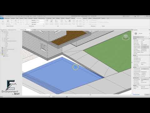
MATCH SLOPE

Slope a Floor or a Roof according to a designated, parallel slab slope.
For example, use this tool to slope a floor by a linked slab.
*NOTE:
- This command can also work on linked floors or roofs.
- You can apply the command on the same floor as many times as you wish.
- You can attach one floor to many sloped surfaces if those surfaces are intersected with or tangent to the floor.
- In case the slabs to be changed have a variable material, some of the options would not be available due to Revit’s limitations.
- Click Environment tab > model element panel > Click on Match Floor
The MATCH SLOPE dialog box opens:
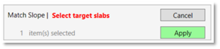
- Select the target floor or roof and click apply.
- Select one or more floors to be sloped according to the previously selected slab.
- Select slabs that partially or fully overlap with the origin slab.
- Click apply.
The MATCH SLOPE dialog box opens:
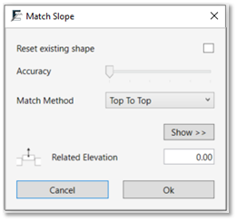
- If a floor or a roof already has a slope, you can reset the shape and apply only the new slope selected by checking the box Reset existing shape.
- To avoid creating heavy elements, leave the accuracy level at the lowest. For greater accuracy with complex shapes turn it up as needed.
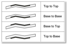
- Select the match method most suitable for you as shown in the icons.
- Select the Related elevation (in relation to the origin surface).
- Click Ok.
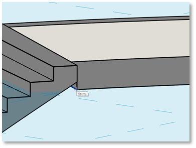
CURB RAMP
Create a curb ramp leading from one Revit slab to an adjoining slab, using a set of pre-defined parameters, to connect the street with the sidewalk.
*NOTE:
- This command works on floors, roofs, and toposolids, for clarity, we will use the term “Slab” in this guide.

 - The resulting Curb Ramp will be a Revit Sub-Element of the selected slab.
 - Within the command you have an option to add an Adaptive Family for scheduling and presentation purposes.
- Click on Environment tab > Site panel > Curb Ramp
The CURB RAMP dialog box opens:
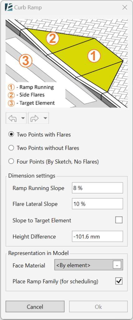
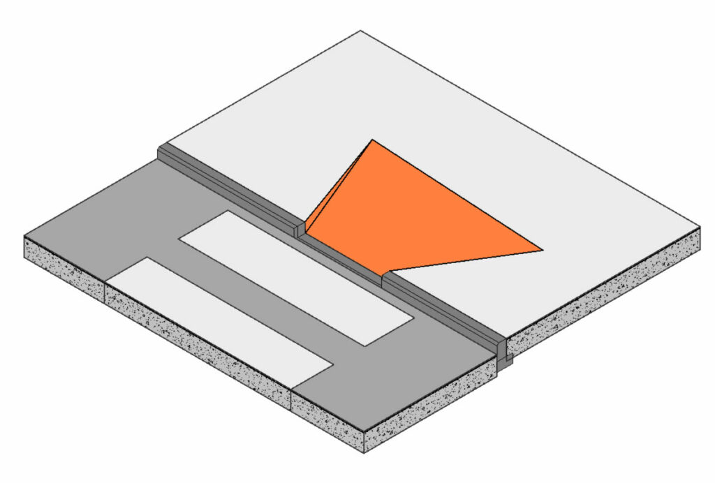
At the top of the dialog box, you will see a diagram indicating the different elements you will need to define in order to create the curb ramp:
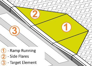
- Ramp Running– the actual sloped surface connecting the Base and the Top of the ramp.
- Side Flares– Triangulated slopes on each side of the ramp, forming the transition to the original slab surface.
- Target Element– The slab you would like to connect the ramp to. The target element can be above or under the original slab i.e. the ramp can go up or down.
*NOTE:
you can Undo or Redoat any point while using the feature, by clicking on the Undo and Redo buttons in the command window.
- To begin, select the Type of Curb Ramp you wish to create:
– Two Points with Flares
– Two Points without Flares
– Four points (By Sketch, No Flares)
- In the Dimension Settings section set the desired parameters
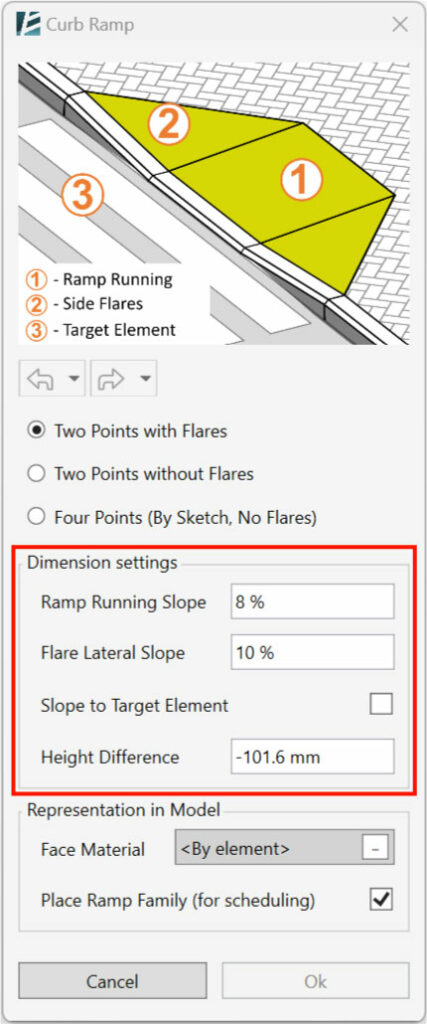
– Set the Running Slope to define the main ramp slope
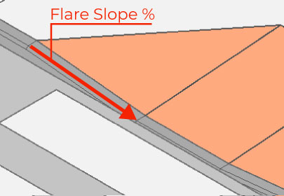
– If you choose to have a ramp with side flares, set the Flare Lateral Slope to define the slopes of the connecting flares. Note that this slope refers to the lateral slope on the edge of the curb (Curbside).
– Set the Height Difference if you want to manually define the height of the slope. Set a negative value for a declining ramp or a positive value for an inclining ramp.
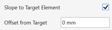
– If you want to set the height according to a selected slab:
Check the Slope to Target Element box. (The Height Difference parameter will be changed to Offset from Target)
– Then, set the Offset From Target value. Keep this value at 0 if you want a seamless connection.
- In the Representation in Model section set the desired parameters

– Select a Face Material for the ramp. This will utilize the native Revit Paint tool to replace the materials of ramp faces.
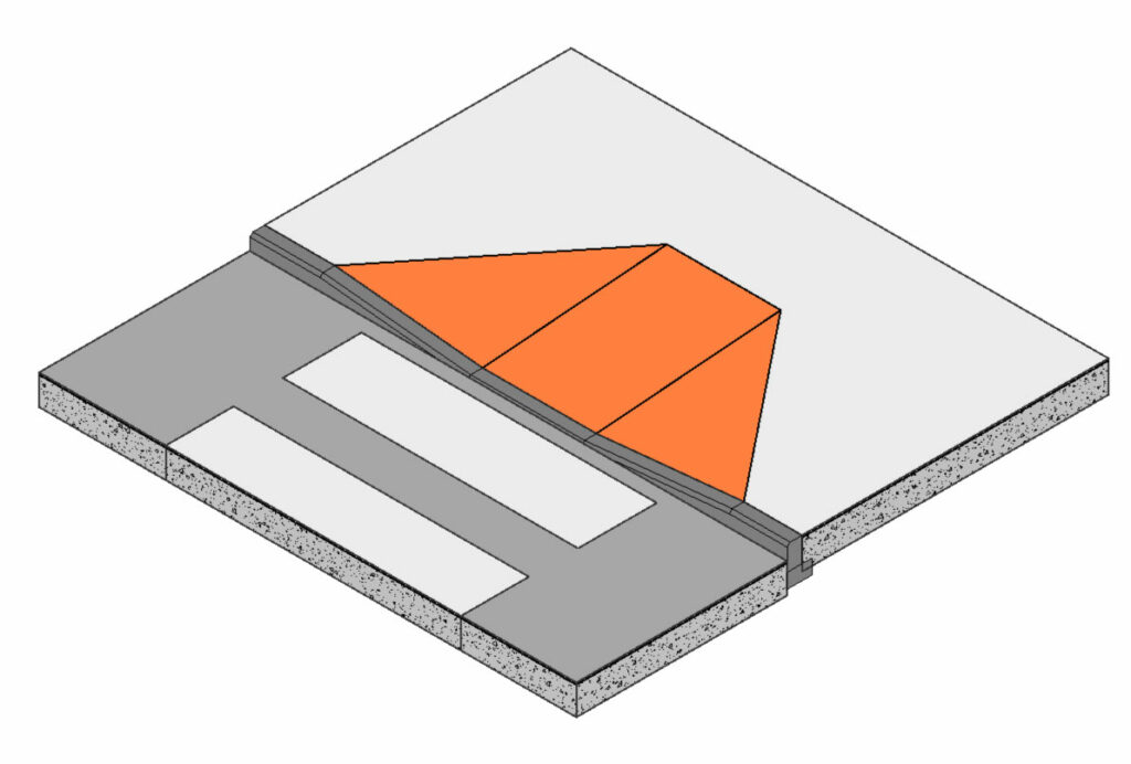
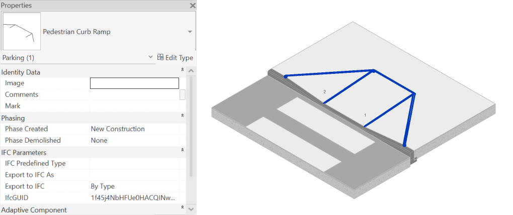
– You can use the Place Ramp Family (for scheduling) to insert an Adaptive Family on the Ramp for scheduling and presentation purposes. See an example of the resulting family in the picture below.
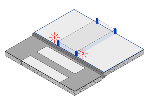
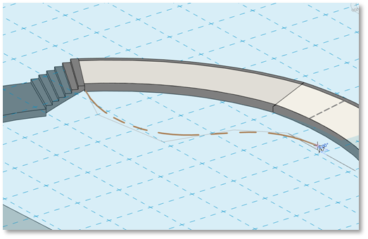
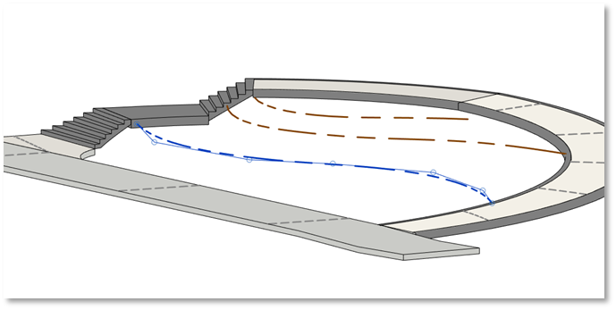
Once you’re happy with the settings, you can start placing the ramp:
- Click on the slab at the starting point of the ramp, then click again on the same slab to determine the ramp width.
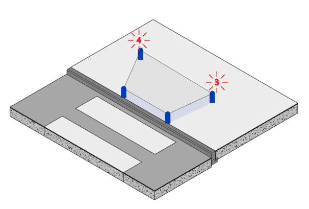
- In case you selected the “Four Points” option – click two more times to define the shape of the ramp.
- In case you selected the “Slope to Target Element” option- click on the Target Element i.e. the road or sidewalk you want the ramp to reach.
- You can keep adding more ramps or use the Undo/Redo buttons to change your preferences as long as the Curb Ramp window is open.
- Click OK to finish and exit the command.
Railings
WALL RAILING
SELECT RAILING
FLIP RAILING
PASTE CURB
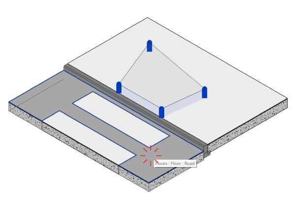
WALL RAILING
Automatically place railing hosted on a wall or chain of walls
- Select the walls.
- Click environment tab > model element panel > Wall railing
or - Click environment tab > model element panel > Wall railing
- Select one or more floors.
- Click Finish.
The WALL RAILING dialog box opens:
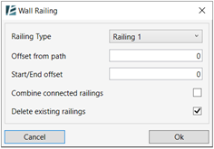
In the Wall Railing dialog box:
- Select the Railing type.
- Type the Offset from path value.
- Type the Start/End offset value.
- Check the Combine connected railings box to convert the number of railings located on connected walls with the same position of the wall top offset into one railing.
- Check or uncheck the Delete existing railings check box.
- Click Ok.
SELECT RAILING

Automatically select all railings on a host.
- Select the host surface or wall.
- Click environment tab > model element panel > Select railings
- Use the Revit selection filter to exclude the hosting element from your selection.
FLIP RAILING

Flip multiple railings at a time. For example, when you need to switch the side of a handrail.
- Select all the railings you wish to flip (you can use the Select Railing command).
- Click Environment tab > Model Element panel > click Flip Railing.
PASTE CURB

Use a railing element to create a curb by picking the edge of a floor, roof, or topography.
*NOTE:
- This command works on all views.
- You can only use railing types that do not contain Balusters, Top rail, or Handrails.
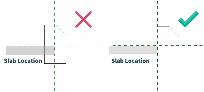
- The profile used for the curb must be located entirely on one side of the family’s insertion point (left or right).
- Click Environment tab > Model element panel > Click on Paste Curb.
- Select the floor or roof on which you want to place the curb (you can also select it before clicking on the command)
The PASTE CURB dialog box opens:
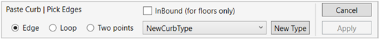
In the Paste Curb dialogue:
- Check InBound box to place the curb within the floor boundary. Environment will then create a fitted opening and put the curb in it. (this option is unavailable when applying curbs on topography or roofs)
- Check Edge to select complete slab edges, in this option Environment automatically selects a chain of connected edges on the surface. If the automatic selection doesn’t fit the design, click again on the same edge to cancel the selection and use another option.
- Check Loop box to apply the curb to the entire perimeter of the selected chain of edges.
- Check Two Points to place the curb on an edge between two selected points.
- Open the drop-down list to select a suitable railing type from your project to be used as a curb. If none is found, click New Type to create a new railing type.
The CREATE NEW TYPE dialog box opens:
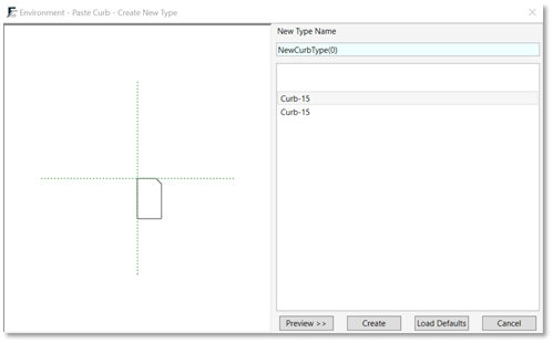
- Click Preview to see the selected curb profile.
- Click Create to create a new railing type from the selected profile, and place it on an edge.
- Click Load Defaults to load suitable curb profiles from the Environment library, and use them to create a new railing type.
- Click Cancel to continue placing curbs.
*NOTE:
- New railing types created with the paste curb command can only consist of one rail. Nevertheless, a railing type with multiple rails can be used as a curb in the command.
- To rename the newly created railing type, exit or complete the command then select the curb and rename the type in the Edit type menu in the type properties.
Model Line Tools
Control line elevation
SET ELEVATION OF MODEL LINE
CHECK ELEVATION
SNAP WORK PLANE
To design accurate and complex topographies, it is common practice to draw contour lines. In Revit, you can use the Model Line category to draw contours in a plan view or a 3D view.
SET ELEVATION OF MODEL LINE

With the Set Elevation tool, you can define and manipulate the elevation of these Model Lines, and later turn them into topography surfaces (Toposurface or Toposolid) using the Add Line feature.
You can set the line’s elevation one by one, or by crossing over multiple lines.
You can set the line’s elevation one by one, or by crossing over multiple lines.
*NOTE:
- Using this feature, you can set the elevation of a chain of lines by clicking on any part of the chain, without the need to select each line segment separately.
 - This feature works in all views.
- • After you’re done drawing the Model Lines, click on Environment tab > Model Lines panel > Set Elevation
Once in the command, you will see the following options in the Options Bar:

- Check the Use Check Elevation symbol box to add annotation on each line indicating its height (See Check Elevation feature).
- In case you add the Check Elevation symbol you can choose the Text Type from the scroll-down menu.
- In the Elevation text box, set the elevation value to determine the elevation of the first model line.
- In the Increment text box set the height difference between the lines, so the next line you select will be of a different elevation. Leave this box at 0.00 to set all lines to the same elevation.
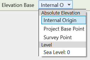
- All line elevations are initially set as relative to the ‘Survey Point’. Use the ‘Elevation Base’ dropdown to choose a different reference point.
- Once you change a line’s elevation, its color in this view will change to indicate the elevation change. You can choose the override color by clicking on the color box next to the Override Color option.
- To set the elevation of a single line, click on it once.
Please note that the Elevation text box in the Options Bar will now indicate the elevation of the next line selected, according to the defined Increment.
Or - To set the elevation of multiple lines at once, use the crossing line function: Simply click once next to a line to start, then drag the dashed line across any other lines you want to modify. Click again when it covers all your desired lines.
*NOTE:
If you used Check Elevation symbols you can manually change the value in a specific text label to modify the height of its connected line.
CHECK ELEVATION

Place smart annotations on Model Lines to show their relative height. Use these annotations to modify the line’s elevation.
- Click environment tab > model lines panel > check elevation
Once in the command, you will see the following options in the Options Bar:

- To keep the text readable, i.e, always oriented to view and never upside down, check the Keep Readable box.
- You can choose the Text Type from the drop-down menu. Please note this list shows all the regular text types in your project.
- All elevation labels are initially shown relative to the Survey Point. Use the Elevation Base dropdown to choose a different reference point.
- To display the elevation of a single line, simply click on it to place the label.
- To display elevation on multiple lines at once, use the crossing line function: Simply click once next to a line to start, then drag the dashed line across any other lines you want to be labeled. Click again when it covers all your desired lines.
- With this option, the text direction will initially show according to the slope descent direction. This will not work if the Keep Readable option is checked.
- To rotate the text direction, open the Check Elevation tool, and click on an existing text label. Please note that this option will not work if the Keep Readable option is checked.
- Please note that you can manually change the value in a specific text label to modify the height of its connected line.
*NOTE:
- Displayed elevation units: Check Elevation labels show the height based on your project's default units.
 - Automatic updates: Once you update the attached line or floor elevation, the label automatically reflects the new value. Deleting the line also removes its label.
 - Moving Labels: Labels can be easily dragged along their attached lines, but they can't be completely detached.
 - Use to annotate Floor contours: Use the "crossing" option to apply Check Elevation labels to multiple lines across floor contours. Updating the floor will adjust both line elevations and their labels. Deleting a single label after using the “Crossing” option on Floor Contours, will prompt you to delete all Floor labels. Selecting "No" keeps the remaining labels, and they'll update when the floor changes.
 - Revit 2022 and Later: For these versions, simply selecting a Check Elevation label will open the Options Bar where you can customize and edit the labels settings.
SNAP WORK PLANE

Create a Work Plane at a selected elevation by picking a reference point in the model, and draw model lines at the elevation of this Work Plane.
Allows an easy and convenient workflow for grading, since you can then use these model lines to create a Topography surface.
*NOTE:
Using this command you can also pick points on linked models (CAD or Revit).
- Click on Environment tab > Model Elements panel > Snap Work Plane
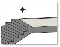
Once in the command, you will see the top ribbon is grey to Indicate you are in the command, and your cursor has a black dot that snaps to all 3D elements.
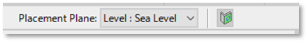
Important:
 Do not change the Placement Plane parameter on the top right corner of your Revit window.
- To place a work plane on a selected elevation, hover over your model, and click on a point in the model.
- You can define the exact elevation of your work plane by entering a value in the WORK PLANE ELEVATION field and selecting the ELEVATION BASE from the drop-down menu in the options bar.
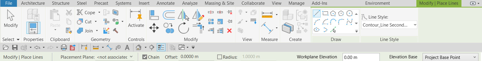
The sketching tools are now available on your Modify tab. Use them to draw Model Lines as contour lines on your work plane.
- Select the desired line style from the drop-down list
- Draw the lines as you wish
- Keep the Chain option checked to draw consecutive lines.
- Set an Offset by entering a value in the corresponding field.
- To create arcs instead of sharp corners, check the Radius box and enter a radius value.
*NOTE:
You can change the elevation of the work plane on the fly while sketching, and the lines you’ve already drawn will remain in place.
- Click Esc twice to go back to Work Plane setting mode.
- Click Esc One more time to exit the command.
*NOTE:
When using the sketch tools, and moving from one tool to another, clicking Esc once will enable you to pick a different tool, clicking Enter will shift between the current and previous tool.
Helpful tip:
 You can edit a line using the same elevation by snaping to it again sketched.
Slab Contours
CREATE SLAB CONTOURS
UPDATE SLAB CONTOURS
DELETE SLAB CONTOURS
EXTRACT SURFACE CONTOURS
Add 3D contour lines and elevation text labels to sloped or modified floors of other surfaces.
CREATE SLAB CONTOURS

Define the line style of the contours and the vertical distance (elevation difference) between these lines.
*NOTE:
- Slabs are floors and roofs
- This command works in plan view and in 3D view.
- Select one or more Slabs (Floors or Roofs).
- Click on Environment tab > Model Lines panel > Slab Contours
or - Click Environment tab > Model Lines panel > Slab Contours
- Select one or more Slabs (Floors or Roofs).
- Click Finish.
The SLAB CONTOUR LINES dialog box opens:
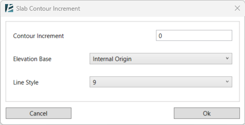
In the Slab Contour Lines dialog box:
- Type a Contour Increment value for the vertical distance between lines.
- Select the Elevation Base from which the contour lines are measured.
- Select a Line Style from the drop-down list (the list will show all line styles available in your project).
- Click Ok.
*NOTE:
- The contour lines will appear on your slabs as model lines.
- The contour lines created using this command will automatically update when you edit the slab.
UPDATE SLAB CONTOURS

Update the appearance, vertical distance and the elevation base of existing contour lines.
*NOTE:
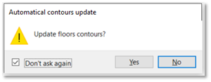
When you update slabs (Floors or Roofs) with contours, Revit asks you whether to update the contours or not. If you click Yes, they will update. To avoid having to wait when editing multiple slabs, click No and use the Update Slab Contours to update all slab contours once your model is ready.
- Click Environment tab > Model Line Panel > the drop-down arrow next to the slab contour line

- Click Update Slab Contours.
The SLAB CONTOUR LINES dialog box opens:
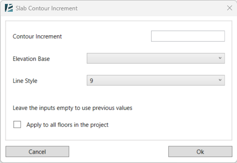
- If changed- Enter a value for the new Contour Increment.
- If changed- Select a new Elevation Base.
- If Changed- Select a new Line Style.
- Select one or more floors/roofs to update
or - Check the box if you wish to apply the changes to all the floors in the project.
- Click Ok.
*NOTE:
You can also preselect the floor you want to update.
 If you do not want to change the values, leave the selection empty.
DELETE SLAB CONTOURS

- Click Environment tab > Model Line Panel > the drop-down arrow next to the slab contour line
- Click delete slab contours.
- Select the slab to delete its contours.
- Click Finish in the options bar to complete the command.
*NOTE:
Using this command deletes all "check elevation" text labels.
EXTRACT SURFACE CONTOURS

Convert toposurfaces to independent model lines.
- Click on Environment tab > Model Lines panel > Extract Surface Contours
- The Command will ask you to choose the toposurfaces you want to convert, you can choose multiple surfaces by leaving the Multiple box checked
- Click Finish when you are done or Cancel to exit the command
Or - Select the topography you want to convert and click on Environment tab > Model Lines panel > Extract Surface Contours
The EXTRACT SURFACE CONTOURS dialog box opens:
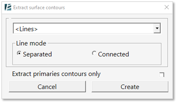
- You can choose the Line Style from the dropdown menu.
- Select whether the lines would be Separated into single lines or Connected into continuous lines.
- Check the Extract primaries contours only box if you wish to convert only the primary contour lines to model lines.
- Click on Create to proceed with the command or Cancel to exit without changes.
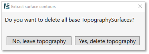
- Environment will ask you whether to keep the original topography in your model or to delete it.
Line Drawing
CONVERT SPLINE

Turn a spline into a chain of lines and arcs
- Click environment tab > Model lines panel > Convert spline
- Click on the spline you want to convert.
SPLIT SPLINE

Divide a spline into two segments
- Click environment tab > Model lines panel > Split spline
- Hover over the division location, then click on the spline.
Geo-location
Coordinate System
SET COORDINATE
Easily Geo-locate or fix coordinates in your project by specifying the preferred coordinate system.
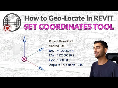
*NOTE:
- Using this tool set your project in a Revit Shared Coordinate system without the need of using the Acquire Coordinates tool.
 - To learn more about Geo Location within Revit please watch this video about shared coordinates.
- Click Environment tab > Geo Location panel > Set Coordinate
The LOCATION WEATHER AND SITE dialog box opens:
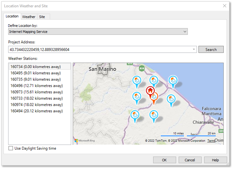
- Type the approximate project address OR type the coordinate’s numbers as Latitude and Longitude in the Project Address textbox and click Search to find the project location.
- You can manually move the red locator pin
 to achieve a more accurate position if needed.
*NOTE:
The location of the red locator pin indicates the location of the project base point (PBP). At this stage, the location of the PBP is only needed for the approximate placement of your project’s geo-location and does not have to be very accurate. You can adjust the location of the PBP at any stage in the future, without affecting the project coordinates.
- Once you are happy with the chosen location click on OK.
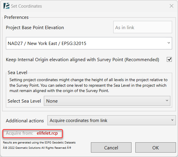
The SET COORDINATES dialog box opens:
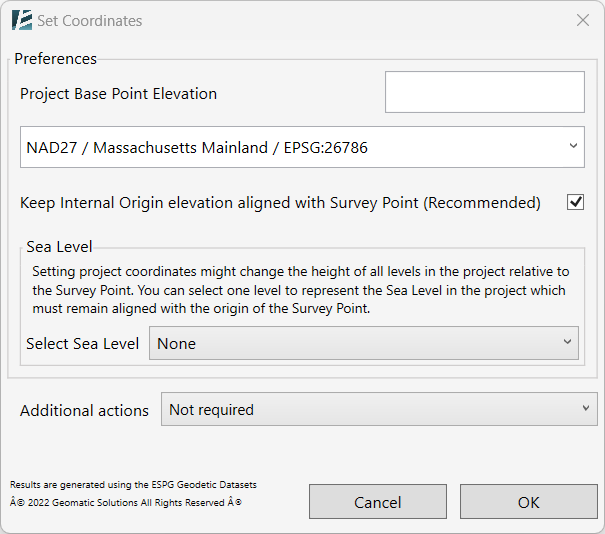
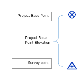
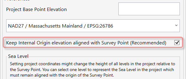
- To change the Project Base Point Elevation, while setting the coordinates, type in the desired elevation value. If your project is located on the sea level elevation, type “0”.
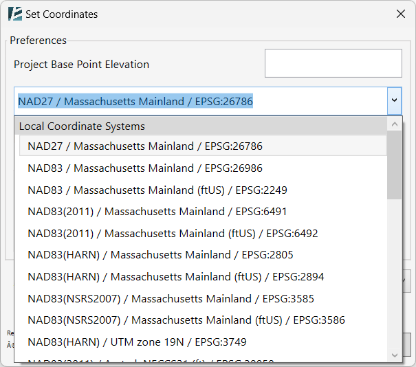
- Select the required Local Coordinate System for your project from the drop-down menu.
*NOTE:
The next stage is optional and will not affect the accuracy of the project, but is a matter of personal preference.
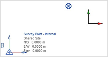
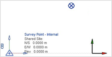
- When the Keep the Internal Origin Elevation aligned with Survey Point (Recommended) box is checked: After setting the coordinates, the Internal Origin will be vertically aligned with the survey point’s elevation.
SEA LEVEL
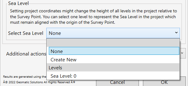
- To have a Revit level used as a Sea level, and to keep it aligned with the Survey point, select a level from the Select Sea Level drop-down menu. Please note, that you can select an existing level or create a new one automatically. If you create a new level, you will see it under the name: “Survey_Point_Base”.
- At this point, you can continue to click OK and set the coordinates of your file, or you can choose one of the following options from the Additional Actions drop-down menu:
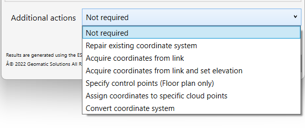
- Not Required– if there’s no need for additional actions.
(Usually recommended when starting a new project) - Repair Existing coordinate system – Use when your file is already within a Shared Coordinate System, and you need to repair it, its elevation, or its geographical location.
HELPFUL TIP:
When working with multiple Revit links, assuming all of the links should share the same coordinates system, you can repair one Revit file with the Set Coordinates command and then repair the other files by linking the repaired file into them. To finish, click on Align option in the prompt window:
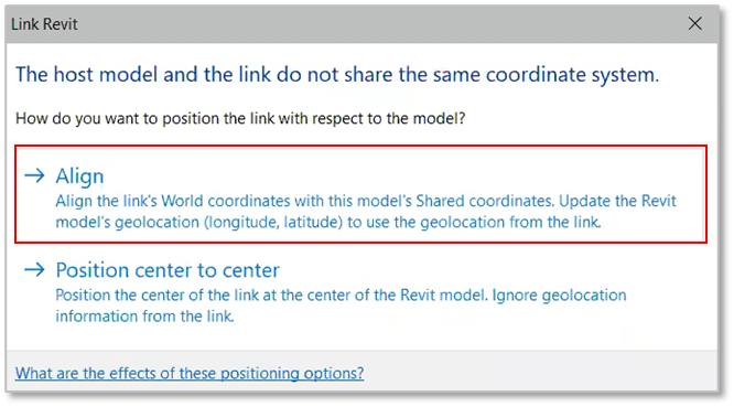
- Acquire coordinates from link – When you want to acquire the shared coordinates from another Revit, AutoCAD, or a Point Cloud file, linked to your model. This action will set the Shared Coordinates for your model, and also geolocate your file, and associate it with the required local coordinates system.
- After choosing this action, select the source linked file from your Revit model space by clicking on it, then, you will see its name at the bottom of the Set Coordinate window.
- Acquire coordinates from link and set elevation – When you want to acquire shared coordinates from another Revit, AutoCAD, or a Point Cloud link while setting the required coordinates system and geo-location you also want to set a new elevation for the PBP.
- After choosing this action, select the source linked file from your Revit model space by clicking on it, then, you will see its name at the bottom of the Set Coordinate window.
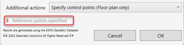
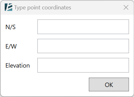
- Specify control points (Floor plan only) – This option is useful when you want to geolocate and set the coordinates of your model, according to a PDF or a JPG survey image, or from some points in a point cloud. You can pick and snap (if available) to any point or element in your model, including DWG, PDF, Point Cloud, and more. Once this option is selected, you can manually type specific coordinates- N/S and E/W values- to selected points in your model.
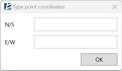
- Click OK to approve each point and you will see a temporary tag showing its coordinates.
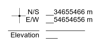
- In the main window, you will always see an indication of how many points you have already selected.
*NOTE:
Make sure to choose at least 2 points to achieve the accurate North position (angle to true north). You can set the accuracy tolerance of these points.
- Assign Coordinates to specific cloud points – Set specific coordinates value to selected points from a linked Point Cloud.
- First, select the linked Point Cloud from your model
- Snap and click to select a point, and specify its N/S, E/W, and Elevation values.
- Once you select and define a point, you will notice a temporary tag showing the information you have entered.
- In the main window, you will always see an indication of how many points you have already selected.
*NOTE:
Make sure to choose at least 2 points to achieve the accurate North position (angle to true north). You can set the accuracy tolerance of these points.
- Convert coordinate system – Use this option to change the local coordinate system in your model while keeping the current geographical location. This is useful when you need to use more than one coordinate system in your project.
*NOTE:
IMPORTANT: Like in any other GIS programs, since every coordinate system has its own accuracy standards, when converting systems- there might be minor inaccuracies.
- Click on OK to finish setting the coordinates.
Interoperability
External Site Data
RHINO ASSETS
GET BLOCKS
IMPORT LIST
EXTERNAL CIVIL DATA
EXPORT TO LandXML
RHINO ASSETS
Bring elements from a Rhino file into Revit and turn them into native Revit elements.

*NOTE:
- This command works with any Rhino files saved in a 3dm format and does not require Rhino to be installed on your computer.
- Click on Environment tab > Interoperability panel > Rhino Assets
The RHINO ASSETS dialog box opens:
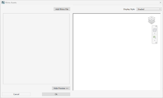
- Click on ‘Show Preview’ to open the preview window and see the imported Rhino model throughout the process.
- Click on ‘Add Rhino File’ to select a file and add it to your Revit model.
The ADD RHINO FILE dialog box opens:
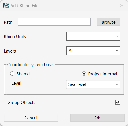
- Click on ‘Browse’ to find the file you wish to import.
Or - You can manually enter the directory path of your Rhino file in the ‘Path‘ text box.
- In the ‘Rhino Units‘ fields- the units used in the Rhino file will automatically show up, however, you can select a different unit format from the drop-down menu.
- The Layers drop-down menu allows you to choose which layers to import. Select All layers to import all, or specify the desired layers from the list.
- In the ‘Coordinate system basis‘ section, you can choose between the ‘Shared’ option, for a shared coordinates system, or the ‘Project internal’ option to import the file according to the internal origin point.
- Select the reference Level for the Rhino model placement.
- To create a single group from the imported Rhino model objects, make sure the option ‘Group Objects’ is checked. (This option is recommended)
*NOTE:
-Maintaining your Rhino Asset as a group is crucial, especially when making modifications to the original Rhino file and subsequently updating them in your Revit model. For further insights on this matter, refer to the "Reload" section within this guide.
- Click ‘OK’ to approve and import the Rhino file, or ‘Cancel’ to go back to the previous window.
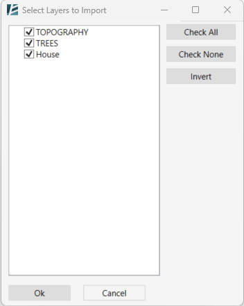
- In case you choose to specify what layers to import, a new Select Layers window will open where you can specify the requested Rhino layers to be imported into your Revit file.
Once you click on OK and approve, you will notice the name of your Rhino file was added to the top of the list, and a small arrow appears next to it.
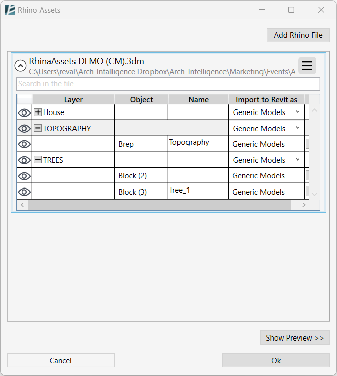
- Click the file name to open a detailed list of the imported layers.
- Click on the Plus (+) sign next to the layer’s name to expand the objects within the layer, and to see the Object’s type, Name, and how they’ll be imported into Revit (what category).
In the “Object” column, you’ll find a list of objects.
If the Rhino file has identical blocks/points, all of the objects with the same block & layer parameters will be consolidated into a single entry in the table where the quantity is indicated in brackets. - Click on the Eye (
 ) symbol in the object table, to hide or show a Rhino element in your Revit model.
 - You can conveniently search for items by Layer, Object, or Name in the Search Bar below the file name.
- Import to Revit as:
– To import an entire layer as a specific category using Direct Shape from Rhino, choose the category from the dropdown menu under the “Import to Revit as” column.
– Click the ellipses (…) icon next to each Rhino object in the “Import to Revit as” column to define its import behavior (e.g., Category, Family, In-Place, etc.).
– You can select multiple objects by holding the Ctrl key while clicking and then clicking on any of the ellipses (…) icons to change their settings altogether.
Once you click on the ellipsis next to an object, a new window will open where you can specify the Revit category of Family of each Rhino object you import.
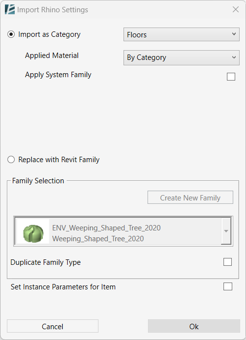
• Specify import options in the IMPORT RHINO SETTINGS dialog box:
*NOTE:
- If you've imported an element as Topography, it's important to note that it will be automatically editable.
However, it's worth mentioning that certain geometries cannot be converted into topography.
- Check the ‘Import as Category’ option to keep the original geometry of the imported Rhino objects, as a Direct Shape and associate it with the selected Revit category.
- You can now select a material to be applied to this object from the ‘Applied Material’ drop-down menu.
- Please note that some Categories (currently: Toposolid and Floors) can be replaced by editable Revit native elements (System Families). If you want to convert the Rhino object into a Revit system Family please check the ”Apply System Family” option. In this case, instead of selecting a material, you can select a family type from the drop-down menu.
- Check the ‘Replace with Revit Family’ option if you want to convert the Rhino geometry into a loadable Revit Family. In this case, you can use the Rhino geometry to create a new Revit Family, or simply replace it with an existing Family.
- To create a Revit Family from the Rhino geometry, click the ‘Create New Family‘ button (Please note that this option is not available when multiple objects are selected).
- A new dialog box will open where you can define the Family Name, Category, and Material.
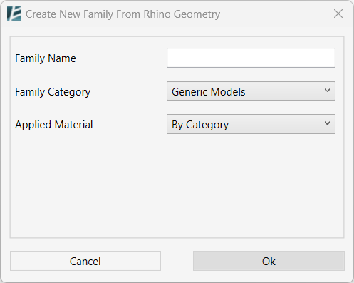
The material can be chosen By Category, Select Manually from the Revit Material Library, or you can make a new Revit material from the Rhino material by choosing the Get from Rhino Display Color option.
- Select the Applied Material for the selected element. Using Revit’s Material selection interface
- Click on ‘OK’ to save changes or ‘Cancel’ to return to the Import Rhino Settings window without saving.
- To replace the Rhino geometry with an existing Revit Family, click on the drop-down list and select the Revit Family you want to use.
- You can check the ‘Duplicate Family Type‘ box to create a new family type for this Rhino element.
- Check the ‘Set Instance Parameters for Item’ box to insert values to available parameters of the instance manually.
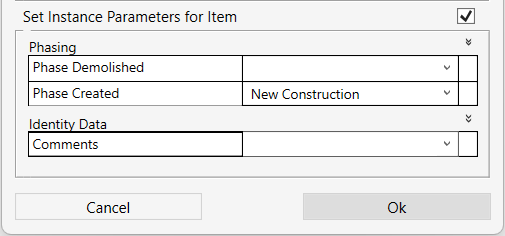
- Click OK to finish or Cancel to go back to the previous window without saving the changes.
- To make changes to the entire Rhino file open the menu at the top right corner:
Click on the Three Stripes Menu Button in the Rhino Assets window next to the file’s name to access the menu for each loaded Rhino file.
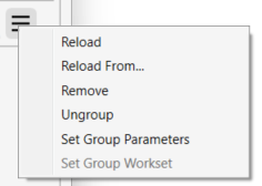
- Click on Reload in case changes were made in the original Rhino file and you would like to update the imported file in your Revit project.
*NOTE:
- When selecting Reload, Environment retains your initially set configurations, which are specific to Rhino objects based on their ID.
- Environment will recognize the position and relative position of the objects from your Rhino file only if you have selected the "Group Objects" option. This means if you moved your objects and they are not grouped you will not be able to update them.
- Click on Reload From… to reload the file from a different location.
- Click on Remove to delete the Rhino file from your Revit project.
- Click on Group/Ungroup to toggle between grouping the elements of the same file and ungrouping.
- Click on Set Group Parameters to edit the available parameters of the group.
- Click on Set Group Workset to assign a workset to the selected group.
- Once you are happy with the results you can Click on OK to finish and insert the Rhino objects into your Revit model.
- Click on Cancel to exit the window without inserting the Rhino File.
- Repeat the process to insert multiple Rhino files into your Revit model.
*NOTE:
At any time, you can go back to the Rhino Assets window by clicking on the Rhino Assets tool and modify the configurations you initially made.
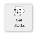
GET BLOCKS
Use blocks from a CAD link to place family instances in the correct location and elevation for your project.
*NOTE:
- This tool works with DWG or DXF format links.
- A group of blocks in Autocad will appear as one block. To solve this, explode the block within Autocad, than save the file and reload into Revit.
- Select the designated CAD link (you may select only one link).
- Click Environment tab > Site panel > Click on Get Blocks.
Or - Click Environment tab > Site panel > Click on Get Blocks.
- Select the designated CAD link (you may select only one link).
The GET BLOCKS dialog box opens:
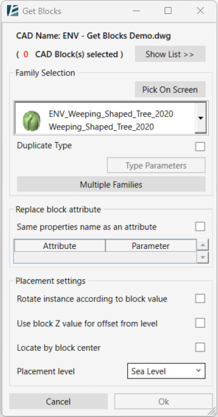
- You can start selecting CAD blocks from your model space.
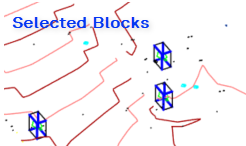
*NOTE:
- Selecting one block will apply the selection of all the instances of the same block
- Selected blocks will be marked with a 3D binding box.
- Click on Show List > > to open the list view of the available blocks in the selected links.
- Select or deselect Blocks from the list.
- Selected blocks in the list will be marked with a blue ✓ sign.
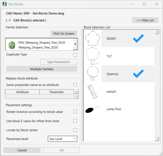
- You can hide the list by clicking on < < Hide List
To replace all selected blocks with the same family
- in the Family Selection section, you can select a family from the drop-down menu
Or - Click on Pick On Screen button to select a Family from your model space.
*NOTE:
- Only families that are not Face Based and that can be hosted on a surface can be selected.
To replace several selected blocks with a different Family for each
- Click on Multiple Families.
The SELECT MULTIPLE FAMILIES dialog box opens:
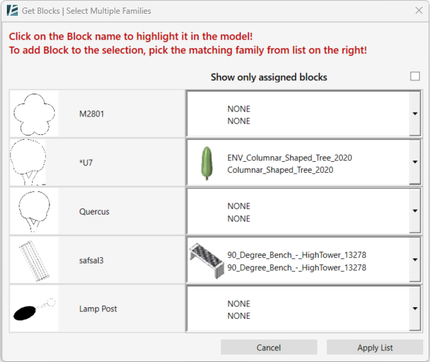
On the left side of the window, you will notice the list of blocks available in the selected CAD link. On the right side, you will notice the dropdown menu to select the associated Family to replace the block.
- You can select a different family for each block on the list using the drop-down menu.
- Click on a block on the left side of the window in order to highlight it in your model space
- Check the Show only assigned blocks to hide all the unselected blocks on the list. (If you enter the Advanced Replacement Settings window when blocks were already selected, you will notice that a default family was assigned to each block.)
- When you are done, click on Apply List to confirm and go back to the previous window or Cancel to go back without saving changes.
Import block’s attributes values to Revit
Using the Get Blocks tool you can import the block’s attributes into Revit Family Parameters.
To Replace the Type parameter it is necessary to create a new type for the family where the attributed can be replaced and not to override existing types in your model.
Instance parameters do not require a new type.
Attributes to Type Parameters:
- To Duplicate Type – and create a new type for the placed instances check the checkbox.
- Once the Duplicate Type box is checked- click on Type Parameters To apply Attributes values from the CAD block.
The DUPLICATE TYPE | NEW TYPE PARAMETERS dialog box opens:
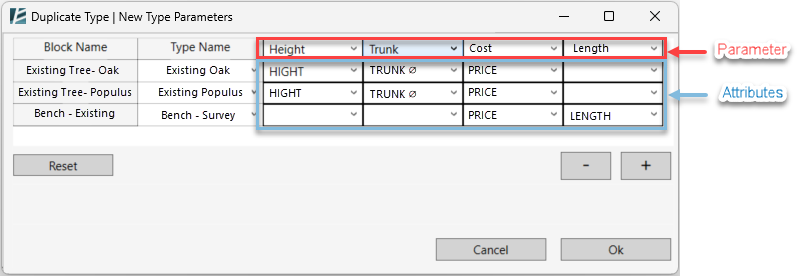
- Each row stands for a different block. Its name appears in the Block Name column.
- Add or remove parameters from the list by using the Plus/Minus buttons
- Select the Type Parameters you want to add by choosing one from the drop-down menu.
- For each block, you can set which parameter value would be inserted in each type’s parameter.
- Click Reset to clear all settings
- Click OK to confirm or Cancel to go back to the Get Blocks window without saving changes.
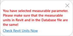
*NOTE:
- When selecting a measurable parameter for your type, a prompt window will show to help you to make sure that the units inserted from the CAD’s attributes are matching.
- To replace Block Attributes values with Instance Parameters refer to the Replace block attribute section
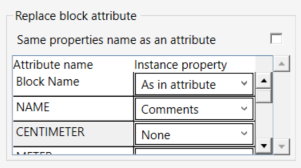
- Check the Same properties name as an attribute checkbox to inherit all Block’s attributes as an Instance Parameter.
Or - Select an Instance Property for each Attribute name in the list from the dropdown menu.
On the Placement settings box:
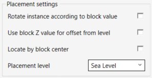
- Check the Rotate instance according to block value to rotate each family instance in your model according to the block rotation property in the link.
- Check Use block Z value for offset from level if you wish to assign elevation to each instance according to the z value in the linked file.
Sometimes, the block insertion point is located outside of the block; - check Locate by block center to place family instances in the center of the block.
- Select a Placement level from the drop-down list.
- Click OK to place the instances in your model or Cancel to exit the command.
IMPORT LIST
import data from an Excel spreadsheet to create topography or to place Revit family instances at specified coordinates and automatically populate the instance parameters of the placed elements based on the data in the spreadsheet.
ideal for workflows involving GIS data, survey points, or external design tools where element placement and parameter data is managed outside Revit.
*NOTE:
- This tool supports *.xlsx; *xlsm; *.csv; *.xml formats.
- Creating topography and placing objects must be done in separate operations. You cannot do both at the same time.

- If your workflow includes creating a spreadsheet out of an AutoCAD file
  - Make sure the CAD file and your Revit model share the same coordinate system and unit format.
  - Learn how to Set Coordinates in Revit.
  - Learn how to Create CSV file from Autocad.
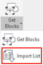
- Click Environment tab > Interoperability panel > Click on the arrow under Get Blocks > Import List
The IMPORT LIST dialog box opens:
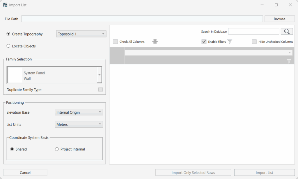
- Click the Browse button, next to the File Path field at the top, to browse and select your Excel file.
- After loading the file, two main options appear in the left panel:
CREATE TOPOGRAPHY
Select the Create Topography checkbox radio button to generate a topography from the spreadsheet
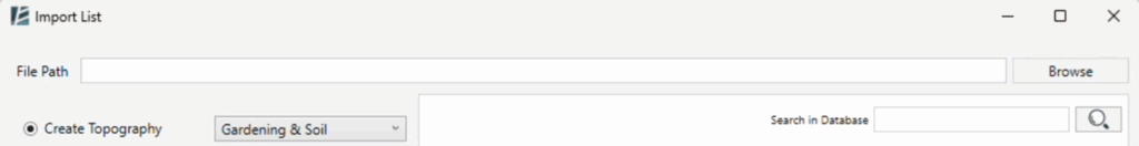
- Choose a Topography Type from the drop-down list of types available in your project.
In the Positioning panel
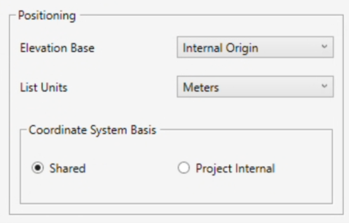
- Select an Elevation Base from the drop-down menu to determine the reference level for your topography.
- Set the List Units to match the unit system used in your spreadsheet file.
- On the right panel you will notice that the spreadsheet data is displayed.
If your spreadsheet contains only three columns, Environment will automatically recognize and assign them in order as X, Y, and Z (Elevation). This automatic mapping can be adjusted manually afterwards if needed.
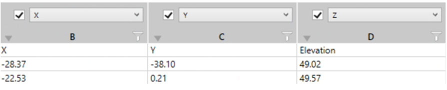
- Check the boxes above each column to activate them for mapping.
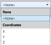
- Use the drop-down list above each column to assign coordinates (X, Y, Z) values.
- Select rows manually and click Import only selected rows.
Or - Click Import List to place all active rows (excluding frozen rows).
LOCATE OBJECTS
Select the Locate Objects checkbox radio button to place Revit families based on coordinate data and populate type or instance parameters.
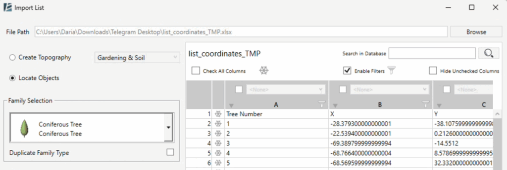
- Choose a Revit Family from the drop-down list.
- Check the Duplicate Family Type checkbox if you want to apply data to Type Parameters; if left unchecked, only Instance Parameters will be available.
- The Positioning preferences are the same as in the “Create Topography” section.
- On the right panel, you will notice that the spreadsheet data is displayed.
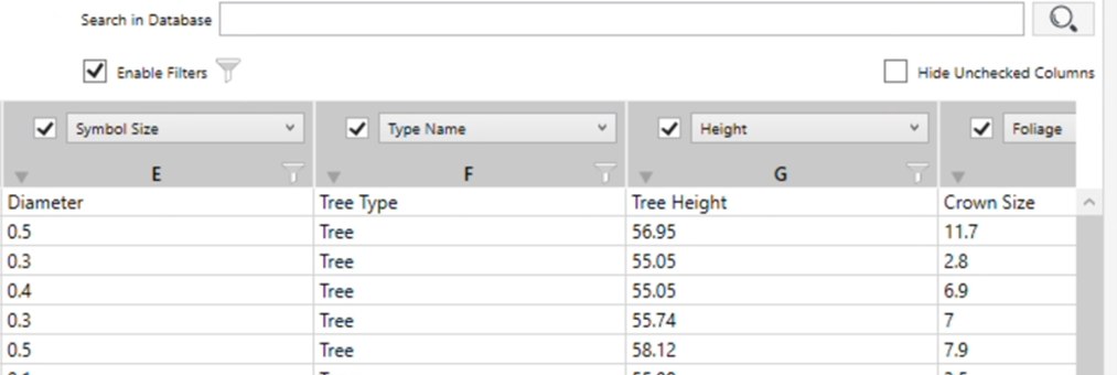
- Check the columns you want to include.
- Use Check all columns to activate all columns at once
- Check the Hide Unchecked Columns checkbox to clean up the view.
- Assign each column to a Revit parameter using the drop-down lists:
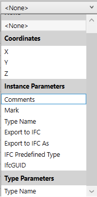
- Coordinates
- Instance Parameters → e.g. Comments, Mark…
- Type Parameters (if enabled) → e.g. Diameter, Height…
- Select rows manually and click Import only selected rows.
Or - Click Import List to place all active rows (excluding frozen rows).
*NOTE:
- Only parameters that exist in the selected family will be available for mapping.
- Parametric families can be dynamically determined (e.g., width, height) using values from your spreadsheet.
- If you don’t pick a parameter from the list above a column, that column will be ignored during import.
ADDITIONAL FEATURES
- Use the Filter
 icon next to any column to include/exclude values.
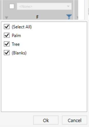
- Uncheck Enable all filters to disable filtering entirely
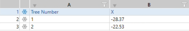
- Click the snowflake icon
 to freeze (ignore) rows from the top down to the selected one.
- Use the Search field to quickly locate values within your spreadsheet.
EXTERNAL CIVIL DATA
Insert and manage information models created by a road engineer in Civil 3D or other programs and exported to a LandXML format.
*NOTE:
Civil engineers, using AutoCAD or CIVIL 3D would usually use shared coordinate system; while it is recommended to work on the same coordinate system as the original XML file, it is possible to use the Project Internal Coordinates if that fits your needs.
- Click on Environment tab > Site panel > External Civil Data
The EXTERNAL CIVIL DATA dialog box opens:
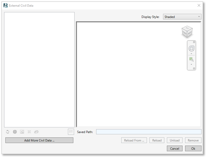
- Click on Add More Civil Data to import a new Xml file into your model
(To manage imported elements see: To modify the imported elements below.)
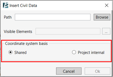
The INSERT CIVIL DATA dialog box opens:
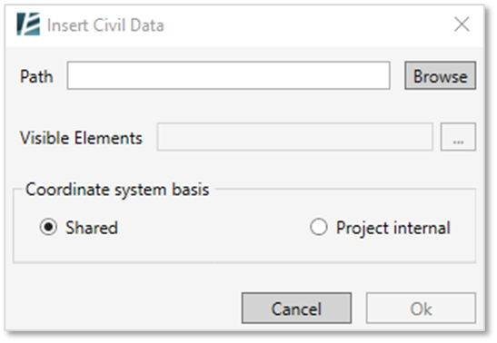
- Click on Browse to select the desired XML file from your computer folders
- In the Visible Elements option – click on the ellipsis (…) button to see the list of elements in the imported file and select which of them to import into your model.
- The Set Visible Elements dialogue has opened, and you will see a list of the civil elements within the file, divided into Topography Surfaces (TIN surfaces in Civil 3D), Roadways (all elements that are part of Civil corridors), and Alignments.
- For Corridors and Alignments- in case there are multiple profiles for the same element (according to the original profiles designed by the engineer), you can choose from the profile drop-down menu.
- You may need to ask the engineer on which profile is best to use.
- Next to each of the civil elements, you will see a checkbox. Uncheck the box of the elements you do not wish to import into your file.
- In the Material column, you can click on the ellipsis (…) button to assign the appropriate material to each element, from the materials loaded into your Revit project.
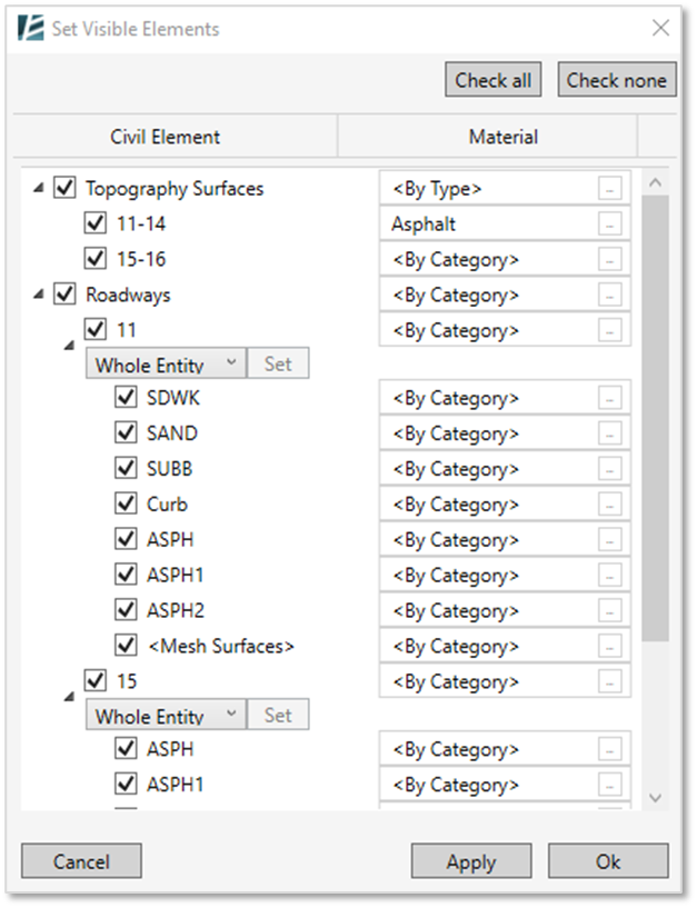
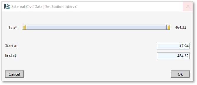
- If you wish to import a specific road segment or station range- click on the Whole Entity drop-down list and select the “Station Interval” option. Click on the “Set” button to open the Set Station interval, and select the required range
- Click Ok to approve and exit the Set Visible Elements menu
- In the “Insert Civil Data” dialogue, Select the Coordinate system basis for the import and click Ok to import the selected elements.
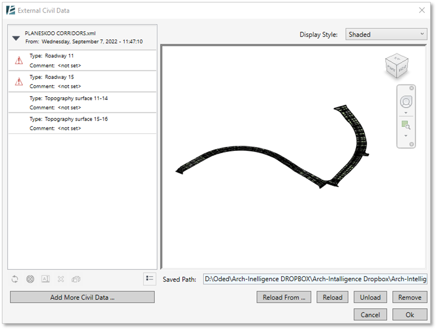
- Once loaded, you will see a list of the imported XML elements on the left section of the “Insert Civil Data” window and a preview of them on the right. You can change the Display Style from the drop-down menu in the top right corner of that window.
*NOTE:
- One of the entities that can be imported is Alignment, which can later be edited and used in The Alignment Tool.
- The imported elements are not editable but you can change their material as well as host elements on them.
- Once files are loaded into your model you can always edit and manage them by going back to the commands main window through the Environment > External civil data.
- Click on Reassign Visibility button
 to turn on/off the visibility of specific elements
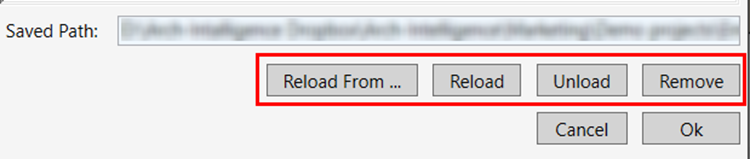
 - On the bottom right corner of the dialogue you can Remove, Unload, Reload or Reload From… a different XML file similar to how you would with any other links (although this isn’t a ‘real’ link)
To modify the imported elements:
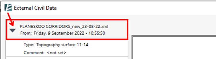
- Click on the drop-down arrow
 next to the XML file name to open the list of its loaded Civil corridors (roads and toposurfaces) and click on an element to modify its properties.
- Click on Rebuild Element
 to reload a specific corridor.
 - Click on Change Materials
 to change material for the different elements of the corridor.
 - *Click on Element Comment
 to set or change the comment displayed on the properties panel when selecting the element in Revit.
 - Click on Delete
 to delete the corridor.
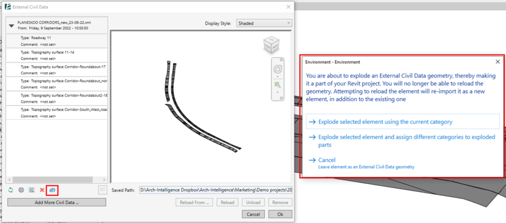
 - Click on Explode
 to integrate the XML elements into your Revit project and make it editable in your model.
*NOTE:
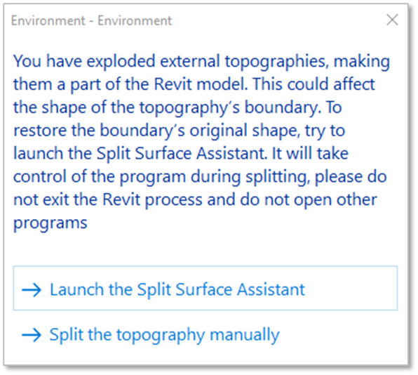
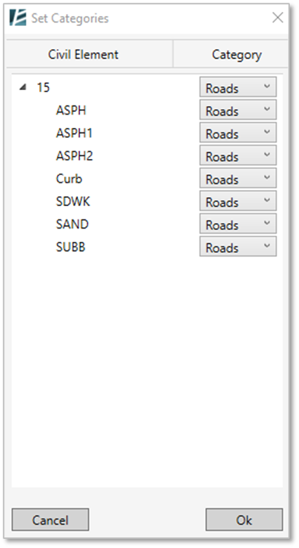
- When exploding a Topography (for Revit 2023 and earlier‣):
 Keep in mind that in order to maintain the accurate slope originally designed in Civil, and because triangulation methods used by Civil and Revit are different, Environment may add points to the surface (in some cases a lot more).
 Consequently, for certain surfaces, calculations might take some time.
 ‣ In Revit 2024 and newer versions: the explode option for Topography is irrelevant since the topography is editable.
 - When exploding a Road element:
 please note that Environment creates a Generic Model, which will remain un-editable but divided into layers such that you can delete each element or add Rebars to it. This is useful if you want to insert reinforcement to the elements or use them in a schedule. Once you click on the Explode button, you can keep the original Revit Category (Road Category) or select the option to Explode selected elements and assign different categories to exploded parts change the desired category for each element on the Set Category window and click Ok to exit this menu
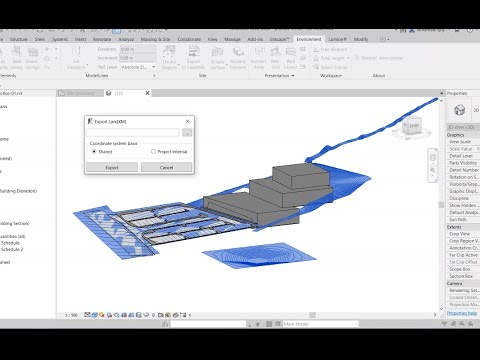
EXPORT TO LandXML
Collaborate with your team and export topographies and slab surfaces to Civil 3D using LandXML file format.
- Click Environment tab > Site panel > Click Export to LandXML.
The EXPORT TO LandXML dialog box opens:
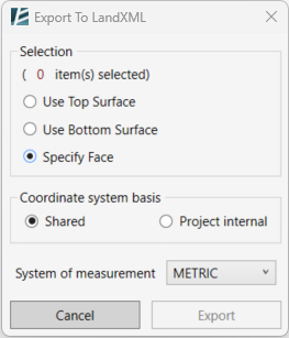
- Use the radio buttons to choose which surface to export:
– Use Top Surface
– Use Bottom Surface
– Specify Face by clicking on it directly in the model - Select the designated surfaces
- Select either a Shared or Project internal coordinate system.
- Select the System of Measurements that will be used in the Civil3D project.
- Click Export to continue or Cancel to exit the command without saving.
- Now specify the save path of LandXML file.
- Click Save.
*NOTE:
- You can also export surfaces from Revit links
- When exported, each surface gets the name according to its Revit name combined with its Revit element ID.
Terrain and Site Components
Topography
TOPOGRAPHY TOOLS
MATCH REFERENCE SURFACE
MODIFY TOPOGRAPHY
ALIGNMENT TOOL
EXTRACT TOPOGRAPHY
CREATE EXCAVATION
FLOOR TO TOPOSOLID
SCAN TO MODEL
TOPOGRAPHY TOOLS
IMPORTANT: This Topography Tools guide is for Revit 2024 and up.
In case you are using an older version expect to see a slightly different interface and functionality.
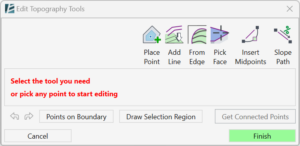
Versions 2023 and below
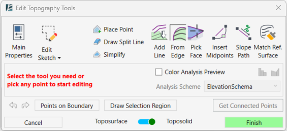
Versions 2024 and above
The Topography Tools command allows you to create and edit Toposolid and Toposurface (i.e., Topographies) using a wide range of features, such as Place Point, From Edge, From Line, and more. While editing or creating a topography, you can switch between tools seamlessly to design your surface and achieve the desired result. In Revit 2024 and newer, you can not only switch the surface’s category between Toposolid and Toposurface, but also visualize Slope and Elevation analyses in real time as you work, making it easier to evaluate and refine the surface interactively during the design process.
*NOTE:
* Throughout this guide, the Term Topography is used to describe both Toposurface and Toposolid (introduced in Revit® 2024).
- To accommodate the Toposolid in Revit 2024 we introduce a new workflow that includes the “Reference Surface” feature and the Extrapolation calculation option which are described in the following guide and the article in the link below.
- For more information about Toposolid and Environment's Topography tools read this article.
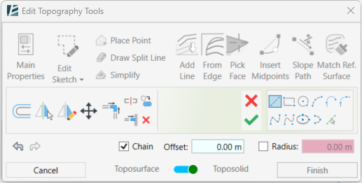
Introduction to the Topography Tools:
You can use the Topography Tools to create a new topography or to edit an existing one.
- To create a new topography:
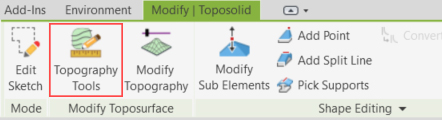
Go to the Environment tab > Site panel > Topography Tools - To edit an existing topography:
Select the topography you want to edit and go to the Modify tab > Topography Tools
*NOTE:
- This command works in all views, and you can easily switch between views while in Edit mode. It is recommended to use the tools only on 3D or Floor plan views.
- The default mode of the Topography Tools is selection mode which allows you to select a point, a split line or multiple points for editing. You can select a point by clicking on it, add to selection with the Ctrl key, subtract from selection by using Shift key, or window-select multiple points at once.
- At any stage of the process, you can click on the Esc key to go back to the default selection menu or click on the Finish button to exit the command.
- At the bottom left of the dialogue you can find the Undo or Redo buttons.
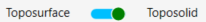
- Use the Toposurface-Toposolid switcher at the bottom of the window to change the surface’s category (from Toposolid to Toposurface or vice versa).
- While in the command, the top ribbon will be greyed to indicate you are in editing mode.

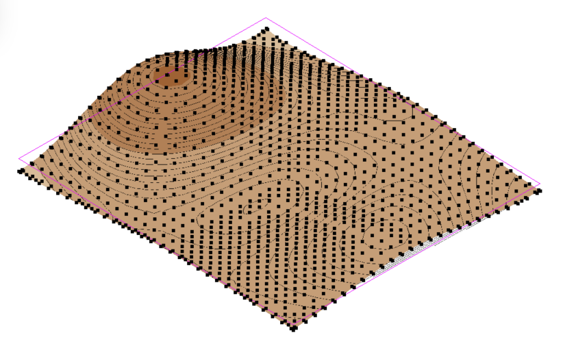
Color Analysis Preview (Revit 2024 and newer)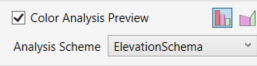
When you check the Color Analysis Preview box in the Topography Tools window, a temporary, color-coded overlay will appear on top of your surface. This visualization helps you evaluate your design in real time.
You can choose between two analysis types:
 Elevation – to visualize the height differences across the surface.
 Slope – to visualize the different surface inclination ranges.
Use the Scheme dropdown menu to select a color scheme for the analysis.
To create or modify schemes, see the Analysis Scheme Tool guide.
NOTE:
If you want the analysis to remain in your model (for documentation or presentation purposes), use the standalone Elevation Analysis or Slope Analysis tools instead. These will create permanent analysis elements in your project.
Advanced Selection tools:
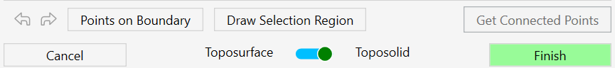
At the bottom of the window, you will find the smart selection tools for the advanced selection of elevation points:
- To select a sequence of boundary points, click on Points on Boundary. Then, pick the first point you wish to select from the surface’s boundary and pick the last point of the sequence. You can use the Tab button to change the direction of point selection. A magenta sketch line will appear to indicate the selection of the points.
*NOTE:
For Revit 2024 and newer versions users:
Points on Boundary will only select the points from the boundary of the Reference Surface, not the actual Toposolid boundary. The Reference Surface is usually larger than the Toposolid boundary, so this selection method does not affect the actual Toposolid boundary.
- To select a group of points within a specified region, click on Draw Selection Region and start clicking to draw the boundary around the points you wish to select. Once you click on Apply Selection Region the points will turn blue to indicate they were selected, and the point editing options will appear in the dialogue.

- To select a group of points with the same elevation (or contour line), pick a point and click on Get Connected Points. You will now see all the required points selected with a magenta sketch line connecting them, and the point editing options will appear in the dialogue.
Once you select a point or a group of points, the point editing options will appear in the dialogue. You can always hit Esc to go back to the default selection mode.
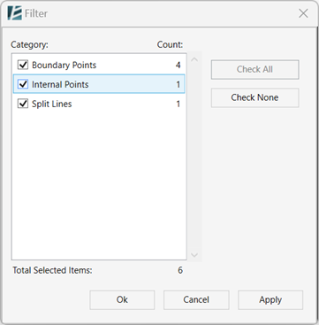
- Use the Filter
 button to refine your selection of elements based on the type of points or lines you wish to select.
Main Properties: (only for Toposolid in Revit 2024 and up)
Once you click on the Main Properties button, a new window will open allowing you to select or change the Type of the element and edit some of its instance parameters such as Comment, Mark, and Phase created all while still in edit mode. Click on Apply to close the Main Properties window and go back to the main dialogue.
Edit Sketch: (only for Revit 2024 and up)
Use this option to edit the surface boundary while staying in edit mode. Once you click on the Edit Sketch button, the menu will be replaced with the sketch tools.
Edit the boundary as you wish, to go back to the Topography Tools, approve (V) or cancel (X) the edit.
Reset Sketch: Remove the existing boundary of the topography
To remove the existing boundary, click the arrow next to Edit Sketch and select Reset Sketch, as a result, the existing boundary will be replaced with a default boundary around the entire surface. Don’t forget, you can always reverse this action by using the ‘undo’ button in the Topography tools window.
*IMPORTANT NOTE:
- If you are using a reference surface you should avoid editing the boundary with Revit native Edit Sketch feature since you will lose your reference surface in the process.
Point Editing Tools:
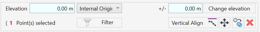
- The Elevation window will automatically show the value of the selected point or show the text <varies> if you select multiple points with different heights.
- Type a new value to change the elevation of a selected point or a group of selected points.
- The drop-down menu next to the elevation value indicates the elevation base of the points. You can set a different reference such as Project Base Point, Survey Point, Internal Origin, or Project Level.
The Change Elevation button allows you to add or subtract height from a selected point or a group of points, relative to its original position. - Once you select the points you want to edit, enter a value in the Change Elevation text box. Use a – sign for a negative value.
- Click on Change Elevation to change the relative height of the points.
- Click on the Delete
 button to delete points.
or - Use the delete button on your keyboard to delete the points.
- Click on the Copy symbol to copy the selected points.
- Check the Multiple checkbox to create multiple copies.
- Click once to set the starting point of the copy
- Click again to set the location of the copied points.
- Click on Move to move the selected points
- Click to set the move starting point
- Click again to set the new locations of the points
- The Vertical Align tool allows you to vertically align the selected points to an intersecting or overlapping surface. You can use any face or surface in your model, including linked elements and topography, as the alignment reference.
- Select the points to align
- Click on Vertical Align
- Select the surface to which you want to align the points.
The selected points will now vertically align to the selected surface or face.
Adding new points to your surface:
Place Point tool:
Revit’s native Place Point tool as you know it, is also available through the Topography Tools and allows you to place Elevation Points in a set elevation.
- Click on Place Point

- From the dropdown menu, select Absolute to insert values in absolute elevation (the height distance from the Internal Origin), or select Relative to Surface to place points on the surface elevation, or a specific reference plane available.
- In the text window, enter the desired elevation value
- Place the points as you wish
- Hit Esc to exit the tool and go back to the start menu and selection options, or select another tool.
- You can also use a spreadsheet (Excel file) to place points based on coordinate data. Click on Import List
 to open the Import List command.
Draw Split Line tool:
The Draw Split Line Tool allows precise editing of the topography by adding interpolable lines. You can draw straight or curved split lines, or you can use splines to draw them on your surface.
- Click on Draw Split Line
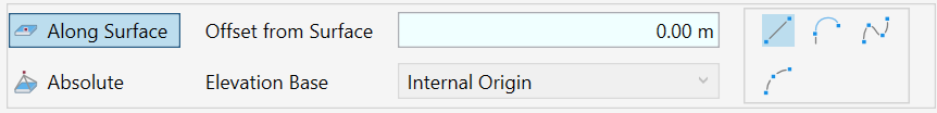
- Use the Along Surface option to adjust the lines to the current surface shape.
- Set the desired Offset from Surface value (keep the value at 0.00 to align the line with the surface)
Or - Choose the Absolute option to draw the lines in a defined elevation.
- By default, all heights are measured about the Internal Origin. You can change the Elevation Base of the line in the drop-down menu. You can choose between Internal Origin, Survey Point, Project Base Point, or a project level.
- Use the sketch tools to start creating your Split Line. You can create straight or curved lines, or create splines, similar to the regular Revit sketch tools. When using Splines, remember to click on Esc to finish drawing.
- Once you draw a line, click on Insert Split Line to approve and add it to your topography.
- Hit Esc to exit the tool and go back to the main topography tools menu and selection options, or you can simply select another tool from the tool’s palette.
*NOTE:
-Few Split Lines may create a chain of Split Lines. Similarly, when creating a curved Split Line, it is automatically converted into a chain of small straight lines.
-When selecting the chain of Split Lines, you can interpolate it. This means that the elevation of the points making these Split Lines will be adjusted to achieve a consistent slope between the first and the last points of the chain.
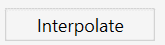
To Interpolate a chain of Split Lines:
- Simply select the subject lines, and you will notice a new Interpolate button will show up (replacing the Filter button) click on that button and see the elevation of the points along the line interpolating automatically.
Simplify:
Reduce and optimize the number of elevation points in a topography.
- Click on Simplify
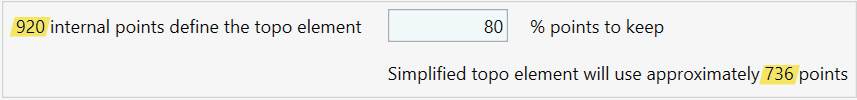
- Enter the percentage value (%) to define the number of points you want to keep on the surface. The number of points before the process will appear on the top left side of the window, and the amount of points after the simplification will appear on the bottom right side of the window.
- Click on Simplify to apply the process.
Add Line tool:
The Add Line command allows you to use selected Model Lines as contour lines for your topography by adding points on top of these lines. You can add Model Lines directly from your model, from a Revit link, or from a CAD file linked to your model. (To set an elevation to Model Lines, see the Set Elevation tool)
- Click on Add Line
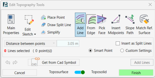
- Pick the lines you want to add by clicking on each line. To add lines to your selection, hold the Ctrl key and pick additional lines, alternatively, you can hold the Shift key to deselect lines. Use the Tab key to select a chain of lines. You can also select lines by clicking and dragging the cursor over a group of lines.
- Check the Insert as Split Lines box to insert the selected lines as Split Lines in your topography.
Controlling the number of points added along a line: - Check the Smart Point option to optimize the number of points added to the lines
or - Check the Custom Settings option to enable the point settings dropdown.
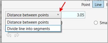
- In the dropdown menu, use Distance Between Points to manually set a value in the distance between points window and control the number of elevation points created.
or - Use the Divide Line into Segments to place points equally along the lines
- Click on Add Lines on the bottom right to add the elevation points to your topography
- Hit Esc to go back to the start menu and select options or select another tool.
Adding lines from a linked CAD file:
This option can be useful when modeling the existing site conditions from a CAD survey in Revit, or when you previously designed your site in CAD and want to incorporate it into your Revit model
- Click on Add Line
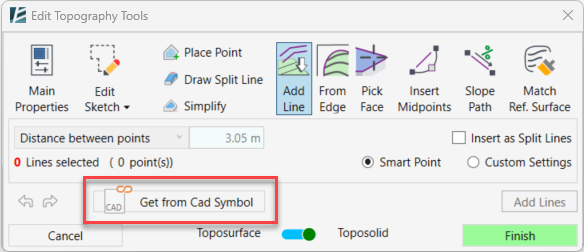
- Click on the Get from CAD symbol button.
- Select the CAD linked in your model by clicking on it.
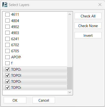
- Pick the relevant layers from the Select Layer list.
- Select the lines from the CAD file by picking each one or by clicking and dragging the cursor over a group of lines. You will notice an indication of how many lines were selected and elevation points were added, marked in red.
- You can also see the name of the selected CAD file at the bottom of the window.
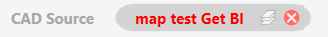
- You can click on the X to remove the selection.
- You can click on the layers
 symbol to edit the selected layers.
 - Click on Add Lines on the bottom right to add the elevation points to your topography.
- Hit Esc to go back to the start menu and select options or select another tool.
*NOTE:
- When adding elevation inside a topography, it is recommended to erase some elevation points in the designated area for a better result.
- The feature to add lines from a linked CAD works best in 3D view. If the linked CAD is set to "current view only" the lines will be added to the topography, but they will result in a flat surface since it is not a 3D link.
From Edge tool (previously Surface from Edge):
Place points along existing model edges in your project. You can pick any 3D edges such as slabs, topographies, walls, or any 3D geometry element, or even linked Revit or CAD geometry.
- Click on From Edge
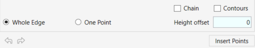
- Click to pick an edge or a point on a face
- Check the Whole Edge option to select complete edges (for example, a line segment, a floor edge segment, etc.)
- Select the Chain option to select a chain of connected edges
- To select the contour lines from topography as a shaped edge, check the Contours option.
- Check the One Point option to pick specific points on an edge or a face
- In the Hight Offset window, set the desired vertical offset value from the selected edge/point. You can change the Hight Offset at every stage of the process before clicking on Insert Points.
- Click on Insert Points to add the points to your topography.
- Hit Esc to go back to the default selection mode or to select another tool.
Pick Face tool:
This tool allows you to place points along the face of any geometry in your project, such as a Roof, a Floor, a Mass, a Topography, or any 3D element including linked elements.
- Click on Pick Face
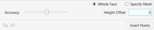
- Use the Whole Face option to select entire surfaces
- Use the Specify Mesh to select specific parts of any solid 3D geometry (such as Floor triangulations etc.)
- In the Hight Offset window, set the desired vertical offset of the points from the selected face. You can change the Hight Offset at every stage of the process before clicking on Insert Points.
- Change the Accuracy bar to control the number of elevation points added to your topography- Keep the bar in the middle to add the exact same amount of points as the original surface.
- Click on Insert Points to add the points to your surface.
- Hit Esc to go back to the default selection mode or to select another tool.
Insert Midpoint tool:
Use this tool to add points as interpolations between two existing points on your surface. The insert Midpoint tool allows you to insert additional points along a straight line or an arc between two existing points to improve the topography accuracy.
- Click on Insert Midpoint
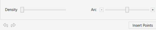
- Pick any two points to stretch a line or a curve between them
- Move the Density slider to change the number of points along the line.
- Move the Arc slider to turn the line into an arc.
- Click on Insert Points to add the points to your topography.
- Hit Esc to go back to the default selection mode or to select another tool.
Slope Path tool:
This tool lets you add points along a defined vector (path) according to a predefined slope value or according to predefined start and end values.
*NOTE:
It is recommended to work on a Floor plan view or set your 3D view to Top projection to make it easier to use the tool.
- Click on Slope Path
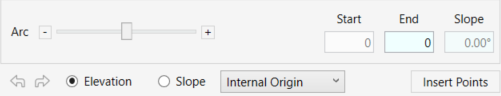
- Pick any existing point on the surface as a starting point for the path
- Move your cursor to set the vector or direction of the path (the magenta line) and click anywhere to place the path’s endpoint.
- Move the Arc slider to turn the line into an arc.
- Check the Elevation option to define the end elevation of the path. You can then see the resulting slope in the Slope window.
- Check the Slope option to define the path’s slope and see the resulting endpoint elevation in the End window.
- Chose the desired reference plane from the drop-down menu
- Click on Insert Points to add the points to your topography.
- Hit Esc to go back to the default selection mode or to select another tool.
Match Ref. Surface: (Works only for Toposolid or Toposurface with a sketched boundary in Revit 2024 and up)
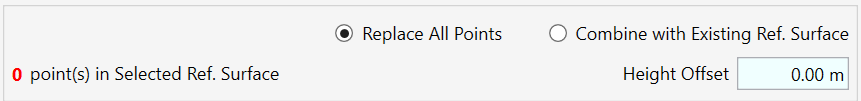
*NOTE:
When using the Topography Tools, using the Reference Surface feature, it's important to make sure the reference surface completely covers the topography's boundary, In the case where the reference surface does not cover the boundary of the topography (as shown in the image)

after you click 'Finish', a warning message will appear. This message provides several options to address this issue:

- Automatically change Toposolid/TopographySurface boundary to match ReferenceSurface geometry- This option automatically modifies the boundary of your topography to align with the geometry of the reference surface.

- Extrapolate Reference Surface slopes. Environment will attempt to predict the height of points outside the Toposolid/TopographySurface boundary- in this option, Environment will use predictive algorithms to estimate the elevation points beyond the Reference Surface boundary. This will fill in missing elevation data. This method results in an estimation which may not always align with your expectations.

- Extrapolate slopes and add new point to Reference Surface. Environment will attempt to predict the height of points and include them into the Toposolid/TopographySurface boundary- Similar to the previous option, this too predicts the height of points outside the Reference Surface boundary and incorporates new elevation points into the Reference Surface. Remember, this method also results in an estimation which may not always align with your expectations.

- Continue editing to manually change Toposolid/TopographySurface boundary as needed- this option returns you to the Topography Tools window. Here, you can manually edit your topography, aiming to resolve the issue of the Reference Surface not covering the Topography boundary.
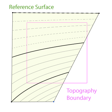
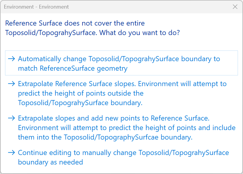
MATCH REFERENCE SURFACE
Easily shape your Topography slope using elevation points from another Topography or Alignment. The points can be outside or inside the new Toposolid boundary.
*NOTE:
-This tool only appears in Revit 2024 or newer versions
-The Referenced Surface (Source Surface) Can either be a Topography or an Alignment.
-This tool would work only if the Referenced Topography was made or edited by Environment’s Topography Tools.
-This tool would work only if the Referenced Alignment has set profiles.
-You can apply this command on one or several Topographies at once.
-You can select the command prior or after selecting the Topographies you wish to edit.
-You can find this command in the Site panel, Modify | Topography tab or in the Topography Tools dialog box.
- On the Environment tab > Site panel > under the Topography Tools drop down> MATCH REFERENCE SURFACE
- Once in the command, select the elements you wish to edit. You can check the Multiple checkbox in the Options Bar to select multiple elements.
- Click on Finish to continue or Cancel to exit the command.
Or - Select the Toposolids you wish to edit, and go to the Modify Toposolid tab > the Modify |Topography Tab> MATCH REFERENCE SURFACE
The MATCH REFERENCE SURFACE dialog box opens:
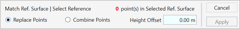
- Select the Topography or Alignmnet to copy its elevation points i.e. Reference Surface. You can only select one reference surface.
Click once to select, and click again on the same surface to deselect. - Check the Replace Points option to replace all existing points with new points from the referenced surface.
- Check the Combine Points option to add the new points of the referenced surface, and keep all existing points.
- Use the Height Offset text box to change the height of the new points.
- At any point, you can see the number of points added to your surface at the top of the dialog box highlighted in red.
- Click Apply to continue and exit the command <please check>.
- Click Cancel to cancel and exit the command.
*NOTE:
In the case where the referance plane doesn not cover the affected topography (as shown in the image, the object topography shown in green)After applying the command the warning message will show:
- Click on Continue without extrapolating to only apply the reference surface where applicable (the rest of the surface will not change its elevation) - Click on OK to extrapolate and let Environment calculate and estimate the topography elevation outside the boundary - Click on Cancel to exit the command without changes
MODIFY TOPOGRAPHY
Smoothly reshape and sculpt any existing topography (i.e., Toposolid or Toposurface) in your model, with the “modify Topography’ collection of tools. Using these tools, you can control the surface as if it was a mesh, inflate or deflate it, or simply smooth the surface or selected areas on it.
*NOTE:
* Throughout this guide, the Terms ‘Topography’ or ‘Surface’ are used to describe both Toposolid and Toposurface. * This feature only works on existing topographies, so you can’t use it to create a new topography. * IMPORTANT: In this process, any existing internal points on the surface will be replaced. * While using the Modify Topography tools you can always keep track of the Topography Data and see how many points were added to your topography.* This command would not work if there are voids in the topography.
- Click Environment tab > Site panel > Topography Tools drop-down arrow > Modify Topography
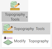
- Select the topography surface you wish to edit
or - Select a topography from your model and click on the Modify Topography tool from the Modify tab
Once you start editing a topography, you will see a 3D blue grid covering it. The grid indicates the places where new elevation points will be added to the surface – a point will be added at every intersection on the grid, so the denser the grid, the more points will be added.
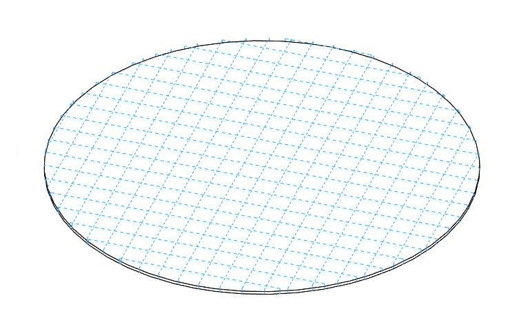
In the Modify Topography dialog, start by inserting the grid settings-
*NOTE:
The grid settings are only relevant when using the Smooth Geometry, Inflate Surface or Mesh Control options, but not for the Shape by Point option.
- Enter the desired Cell Size value to define the grid density. This will affect the amount of elevation points on the topography and consequently also the smoothness of it.
- Use the Rotation slider to set a rotation angle to the grid. The rotation might have a significant influence on the end result, so a trial-and-error approach is recommended here.
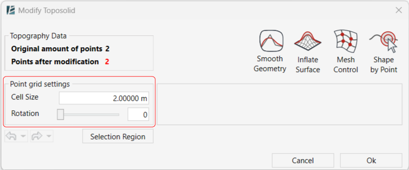
- If you wish to edit a specific area within the selected topography, click on the Selection Region to delimit an editing boundary on the surface.
- Next, select any of the following tools to edit your surface :
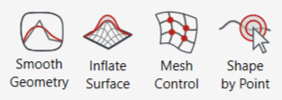
*NOTE:
- On the left side of the window, you will find the Redo & Undo buttons, with a drop-down arrow to choose from a list with your latest actions.- At any stage, you can click Ok to complete the process and exit the command.
- To smooth the selected topography, click on Smooth Geometry
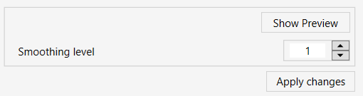
- Define the wanted Smoothing Level. You can set a level from 1 to 4.
(you might need to apply this tool a few times till you get the desired result)
- Click on the Show Preview option to see a preview of the result without leaving the command.
- Click on Apply changes to complete the process.
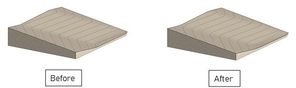
- Click on Inflate Surface to inflate or deflate the topography, and create a mound or a basin.
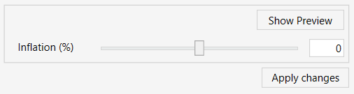
- Move the Inflation (%) slider to define the relative height or depth of the surface. You can set any value, from -50% to 50%. Set a negative value for deflation or a positive value for inflation.
- Click on Show Preview to see the result without leaving the command. You can then move the slider and click on Show Preview again until you are happy with the shape of the surface.
- Click on Apply changes to complete the process.
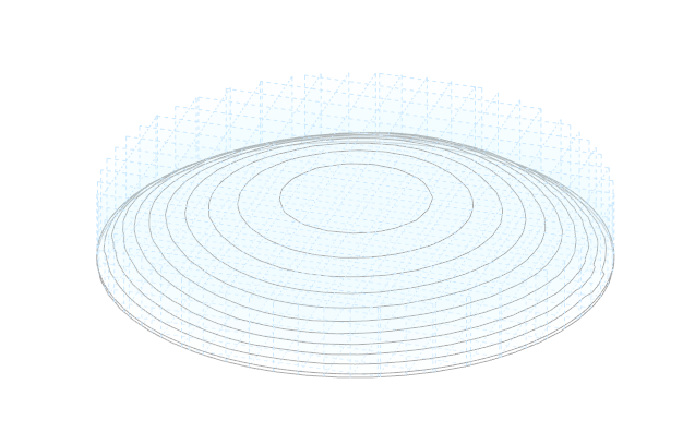
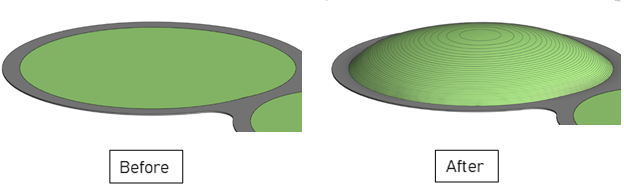
- Click on Mesh Control to design the surface using nodes on a grid, which you can freely move in any direction using control handles.
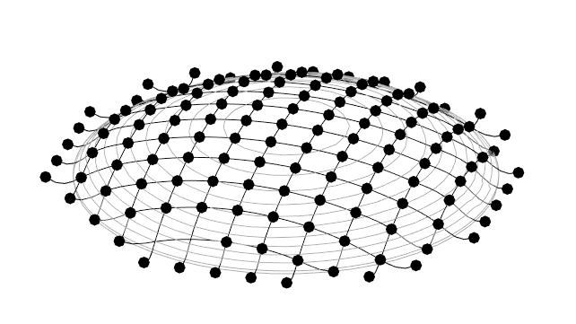
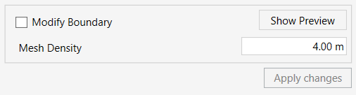
- For Toposolid only (Revit 2024 and newer): Check the Modify Boundary checkbox to control nodes located outside of the Topography boundary.
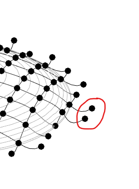
- Set the Mesh Density to change the spacing of the control handles on the Mesh grid. (Note- changing this does not affect the Cell Size option in the point grid)
- Click on a node to select it, and use the 3D control handle to move it in any direction- up, down, left, or right. As you move the handles you will see the lines changing to indicate what would be the end result.
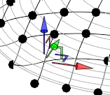
- Click on Show Preview to see the changes. You can keep moving the nodes and click on Show Preview again until you are happy with the topography design.
- Click on Apply changes to complete the process.
- Click on Shape by Point to place a cluster of elevation points in a way that inflates, deflates, or smooths the surface around a specific point. This way you can quickly create a local mound or pond in one click.
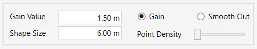
- Choose the Gain option to inflate or deflate a point:
- Set the Shape Size to define the circle diameter.
- Move the Point Density slider to adjust the amount of points added to the circle. (The more points you add, the smoother the resulting shape will be).
- Set the Gain Value to determine the overall height of the hill. You can set a negative value to create a basin. Note that the gain value is relative to the existing shape of your selected surface.
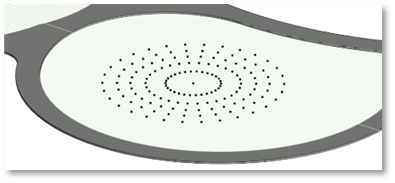
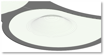
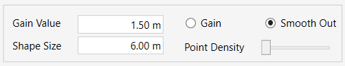
- Choose the Smooth Out option to smooth an area on your surface by clicking on a specific place you want to smooth out:
(Try to click more than once on one place for a better smoothing result)
- Set the Shape Size to define the smoothing diameter.
- Move the Point Density slider to adjust the amount of points added in every click. (The more points you add, the smoother the resulting shape will be).
- click on Ok or Cancel to finish the command and exit
ALIGNMENT TOOLS
Design roads and pathways using the Alignment Category in Revit.
An alignment is a native Revit category, originally designed for collaboration with infrastructure projects and Civil disciplines. It is a 3D line that represents the center of a certain road or a pathway.
Using the Alignment tool, you can define the elevations and slopes of each part of the Alignment as well as add a Cross-Section to control the roads’ width and overall shape.
Once your alignment is done, a reference surface is embedded in it, so you can extract a topography that follows your road design.
*NOTE:
- The created Alignments are an ‘Infrastructure Model’ System Family of the ‘Alignment’ category. They cannot be moved, copied, or edited with native Revit tools, rather they can only be edited using Environment’s Alignment tools.
- This tool works in all views, though it is recommended to work in a 3D view or in a Floor Plan view since the Drawing Mode does not work in Section or Elevation views.
- You can import an Alignment from Civil 3D using the External Civil Data tool and edit it using the Alignment tool.
- This tool is only available for Revit version 2021 and newer.
- It is important to note: The Alignment is composed of a continuous chain of line segments, where all curved transitions between straight segments are generated based on rules applied to the associated control points.
- Click on Environment tab > Terrain and Site Component panel> Alignment Tools
The ALIGNMENT TOOLS dialog box opens:
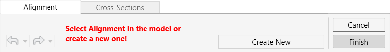
To start, you can either create a new Alignment or select an existing Alignment from your model:
To select an Alignment, Click on an existing Alignment in your model space. (See below: “When an Alignment is selected”)
To create a new alignment:
- Click on ‘Create New’ to start drawing a new Alignment.
- In the ‘Create New Alignment’ window enter the Alignment Name and click OK to continue or Cancel to go back.
- Once you click Ok, the drawing mode will appear in the Alignment window. Draw the Alignment element using the drawing tools.
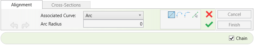
- In the Associated Curve drop-down menu, select the desired curve type: Arc or a spiral option)
- Choose Arc to create a circular transition curve. When Arc is selected, set the desired value in the Arc Radius field to control the curvature.
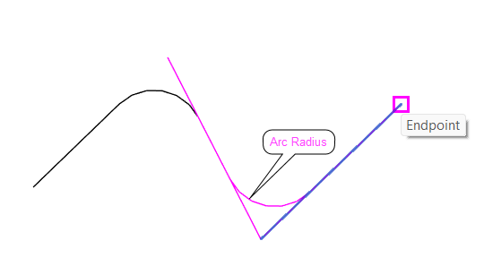
- Choose one of the Spiral options to create a transition curve with a variable radius. When a Spiral option is selected, click on Curve Settings.
NOTE:
- Use an Arc when a constant-radius curve is sufficient.
This is typically suitable for low-speed roads and simple paths.
- Use a Spiral when a gradual transition between a straight segment and a curved segment is required.
The CURVE SETTINGS window opens.
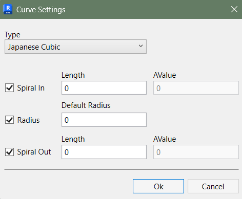
- From the Type drop-down menu, select the desired spiral type.
- Check the Spiral In checkbox to enable or disable the incoming spiral segment.
When enabled, set the Length value to control its geometry. - Check the Radius checkbox to define a constant radius section between the spiral segments.
Set the Default Radius value to control the radius of the main section. - Check the Spiral Out checkbox to enable or disable the outgoing spiral segment.
When enabled, set the Length value to control its geometry. - Click OK to apply the settings and return to the Alignment editing mode or Cancel to discard the changes.
- Keep the Chain checkbox checked to draw sequenced lines continuously.
- While drawing, you can use the integrated Undo or Redo buttons

- Switch to editing mode: Press the Esc key once to enter Editing mode and edit the Alignment
 You can continue drawing by selecting anyof the drawing tools again.
 - Finalize your drawing: Click the green ✔ button to apply the changes, exit editing mode, and return to Selected mode.
When an Alignment is selected:
Once you select an existing Alignment from your model, the Alignment window will update to display the available options, and the chosen Alignment’s name will be highlighted in red under “Selected”. (in order to select a different alignment- you must close the Alignment tool and re-enter)
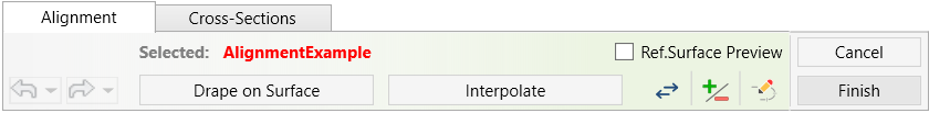
- Keep the Ref. Surface Preview box checked to see a preview of the reference surface, i.e., the resulting path. (This preview will only be visible once a Cross-Section is added).
- Click Drape on Surface to project the Alignment onto your chosen topographies. Then, select one or more topographies from your model. To deselect a topography, click on it again.
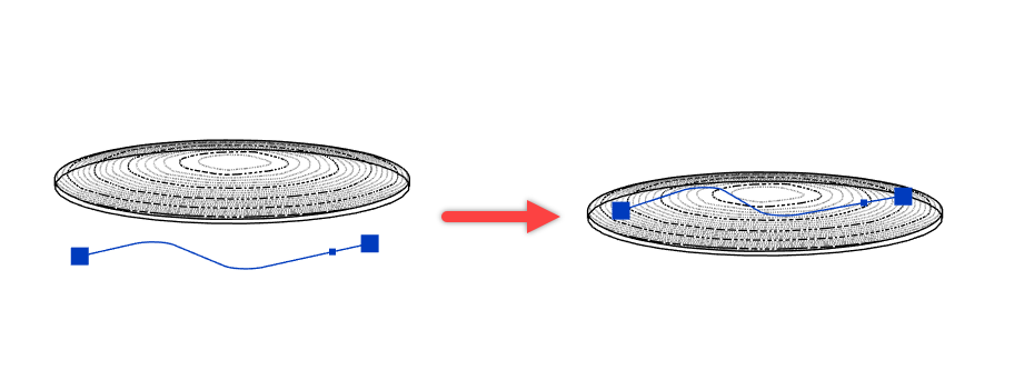
The following options will appear in the Alignment window:
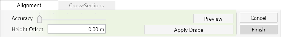
- Set your desired Accuracy level. Please note: to get a smoother path with fewer vertices, keep a low level of accuracy.
- Set the desired Height Offset of the path from the selected surface.
- Click on Preview to see the result before applying.
- Click on Apply Drape to approve the settings and go back to Editing mode.
- Click on the Flip Alignment
 button to change the Alignment’s direction, indicated by the blue arrows at the beginning and end of the Alignment.
- Click on Interpolate to create a uniform slope between the Start and End points of the selected Alignment. This is particularly useful after manually adjusting the elevations at the start and end points. Using Interpolate will automatically adjust the Alignment segments so that they follow a consistent slope.
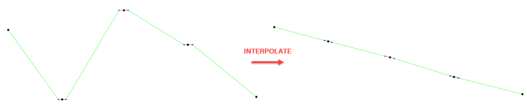
- Click on the Add and Remove
 button to insert or delete Vertices or Control Points along an existing segment.
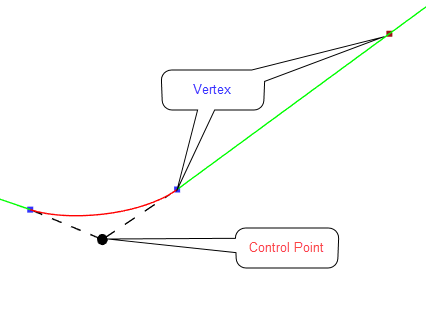
*NOTE:
- Changing the Alignment direction will affect the direction and position of previously applied Cross Sections.
- It will also affect the Stations' numbering, as it is associated with the distance from the start of the Alignment.
- Click Edit Alignment
 to go back to the drawing tools for the selected Alignment.
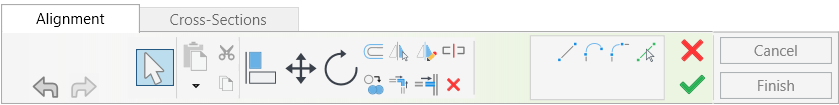
In Drawing Mode:
- Click on any segment or Control Point along the Alignment to select it for precise editing.
- When a Control Point is selected, the Edit Control Point menu will open, allowing you to modify the Associated Curve and adjust its parameters.
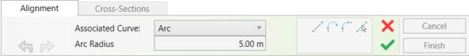
Back in Selection Mode:
Allows you to keep editing the Alignment outside the Drawing tools
- Click on any segment or control point along the Alignment to select for precise editing. You can select multiple elements using a selection window.
- Click on the Filter icon
 to refine your selection between Vertices, Control Points, and Segments.
 - When selecting multiple Segments or Vertices, you have the option to Interpolate only selected elements.
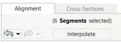
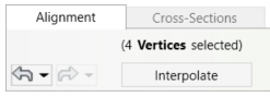
- When selecting a control point, a 3D control handle will appear on the point in the model, allowing you to drag it freely to adjust its position in any direction.
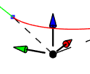
The Alignment window will display the relevant editing options for the selected point:
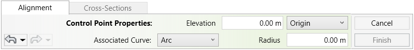
- Select the Associated Curve (Arc or a spiral) from the dropdown menu.
- Enter a value to adjust the radius of the curve connected to the selected point. (or set the Spiral Settings in case you selected a spiral)
- Change the Elevation value to adjust the height of the Control point.
- You can choose the Elevation reference base from the dropdown menu next to the elevation text box.
- Click on Esc key to go back to Selection mode, and to continue editing the Alignment.
- When selecting a Vertex along an existing segment, you will notice the up and down arrows. Drag these arrows to manually change the elevation of the Vertex.
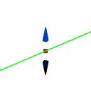
The Alignment window will display the relevant editing options for the selected vertex:
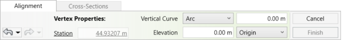
- Change the Station value to adjust the position of the vertex along the path. (the value is calculated from the starting point).
- Select the Vertical Curve Arc and set the value to allow curved connections between adjacent segments.
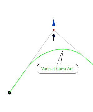
- Change the Elevation value to adjust the height of the selected point.
- You can choose the Elevation reference base from the dropdown menu next to the elevation text box.
- Click on Esc key to go back to Selection mode, and to continue editing the Alignment.
- When selecting a segment along the Alignment, be it a line or a curve, a 3D control handle will appear on the segment in the model, allowing you to drag it freely to adjust its position in any direction.
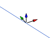
The Alignment window displays the relevant editing options for the selected segment.
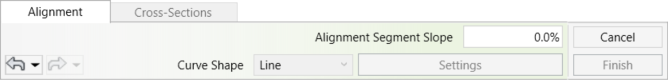
- Set the Alignment Segment Slope value to define the slope of the selected segment. As the slope is defined by the direction of the Alignment, this change will affect only the elevation of the point at the end of the segment.
- If a curved segment is selected, you can also define the curve type (Arc or Spiral) and adjust its parameters.

- Click the Esc key to return to the previous Selection mode and continue editing the Alignment.
CROSS SECTION
To insert and manage Cross-Sections (profiles) along the Alignment, go to the Cross-Section tab.
This tab is available only when an Alignment is selected.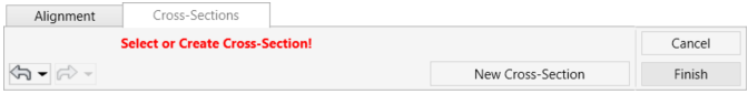
- To add a new Cross-Section, Click New Cross-Section, then click anywhere along the selected Alignment to place the section.
- To edit an existing Cross-Section, click the Cross-Section directly along the Alignment.
- Once a Cross-Section is placed or selected, the Cross-Section menu becomes available
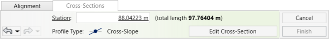
- To change the location of the Cross-Section, edit the Station value of the selected section.
- Click Edit Cross-Section to open the Cross-Section Edit menu:
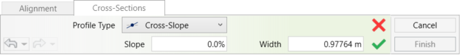
- In the Cross-Section Edit menu, select the Profile Type from the drop-down list.
- Cross-Slope

Use this option to define a standard cross-section profile.
– Set the Width value to control the overall width of the section.
– Set the Slope value to define the side slope of the section.
- Cross-Slope
Keep the Maintain Transition Shape checkbox checked to preserve the original path shape defined by the different Cross-Sections.
When the checkbox is unchecked, the Break Point Cross-Section will replicate the shape of the nearest preceding Cross-Section.
- Align to Edge
This option is available only for Cross-Sections located at the start or end of the Alignment.
- Use Align to Edge to trim the path edge and align it with a selected model edge.
- Set the Width value to control the width of the path.
- Click the target edge in the model to align the path accordingly.
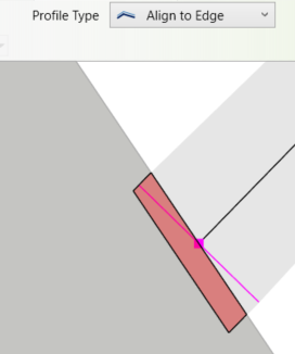
- Profiles
Use this option to define the Cross-Section profile using Profile Families.
You can create custom Profile Families, similar to those used for Railings.
Once a suitable Profile Family is loaded into the project, it appears automatically in the Profile drop-down list within the Cross-Section tab.
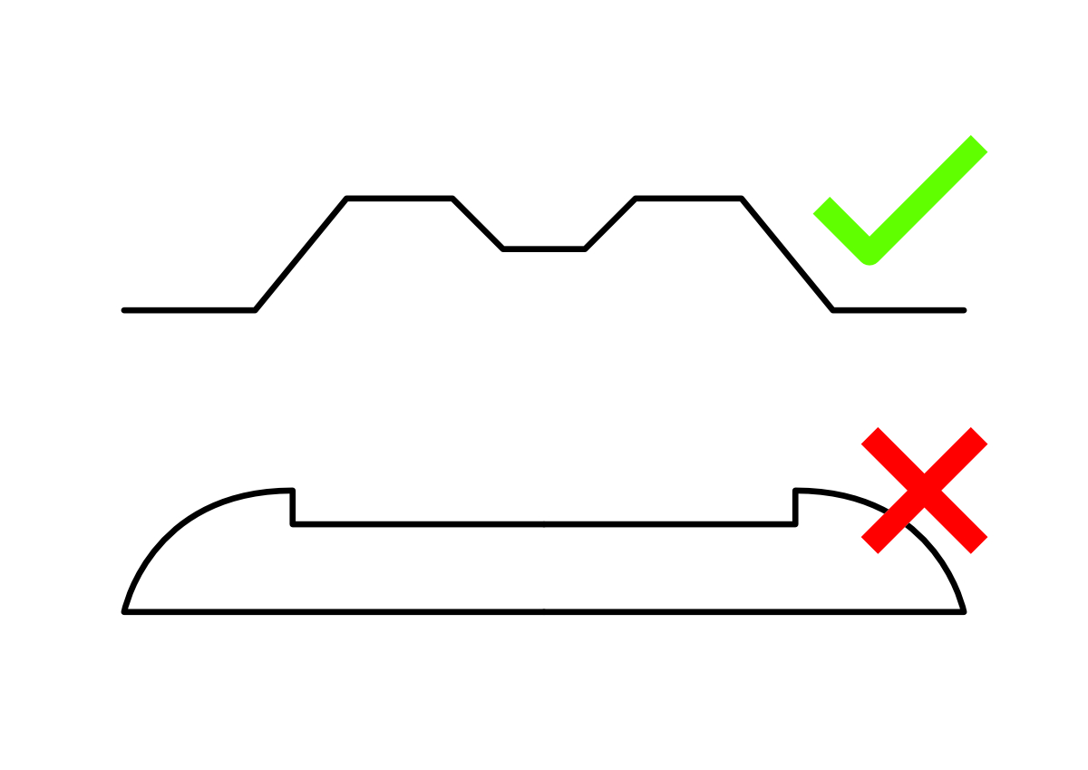
- Profile Families define only the top surface and do not include width.
- Profile Families currently do not support curved geometry.
- Click on the green V to Apply or the red X to cancel and go back to the Edit Cross Section menu
- Click the Esc button on your keyboard to go back to the main Cross section tab and add more cross sections if needed.
- Click on Finish to complete the command or Cancel to exit the command without saving changes.
*NOTE:
- After adding a cross section to the alignment, a Reference Surface is embedded in it.
You can use the alignment as a reference surface for other purposes- read more about Reference Surfaces in the Match Reference Surface tool.
Terms used in thE ALIGNMENT TOOLS’ user guide:
–Alignment: a 3D line composed of Alignment segments (straight lines and transition curves), control points and vertices. You can think of it as the centerline of your path.
–Transition Curves: A 3D curve that connects and tangents between two adjacent lines. The curve can be an arc (Circular) or a spiral (Asymmetric or Parabolic)
–Control Points: Appears at each end of a straight line. They help you define the connection between lines and the shape of adjacent Transition Curve. You can think of them as similar to the control handles in a spline, except they can move in any direction in the 3D space.
–Vertices: Key Points along your Alignment, that allow you to control the elevation. Each Vertex can have its own Vertical Curve associated with it. Unlike Control Points, Vertices can only move up and down.
–Station: A reference to any point along the Alignment path. Each station is assigned a unique number that represents its distance from the starting point of the Alignment.
–Cross-Section: The shape of the road cross section (profile) at a specific Station.
–Reference surface: an abstract surface created from the Alignment and its cross-sections. This surface can be extracted as a topography or a Toposolid to use in your project.
EXTRACT TOPOGRAPHY
Generate a topography surface based on an existing Alignment element in your Revit model (see “Alignment Tool” section for instructions on creating Alignments).
*NOTE:
- This tool requires an existing Alignment with at least one defined Cross-Section within it. Cross-Section profiles provide necessary data of the width and cross slope of the surface.
- You can preview the reference surface plane while creating the Alignment to get a better idea of what the resulting topography will look like once you extract it. To do this, enable the "Ref. Surface Preview" checkbox within the Alignment Tool dialog window.

- This tool is only available for Revit version 2021 and newer.
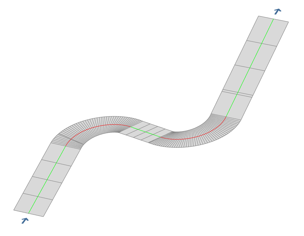
- Go to
Environment tab > Terrain and Site Component panel >Alignment Tools drop-down arrow > Extract Topography
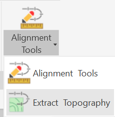
- Once you selected the tool, pick the Alignment from which you want to extract the topography surface.
In Revit versions 2021 through 2023:
- The Extract Topography tool will now generate a new Toposurface will be created within your model, based on the selected Alignment.
In Revit versions 2024 and up:
The GENERATE TOPOSOLID dialog box opens:
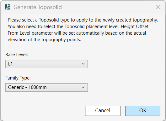
- Select the desired Base Level to associate with the new Toposolid.
- Choose the desired Family Type for the Toposolid.
- Click OK to finish the operation and generate the Toposolid.
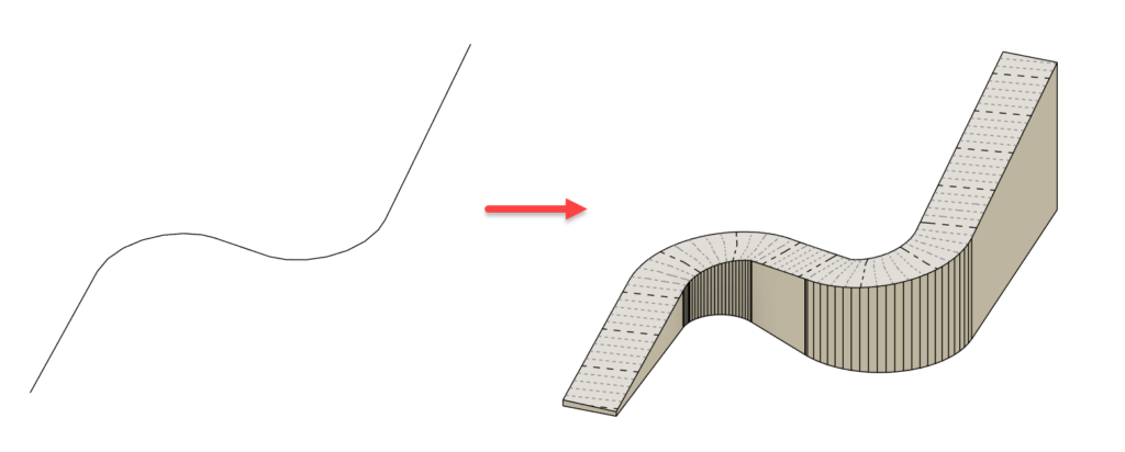
- Click Cancel to exit the command without changes.
CREATE EXCAVATION
Automatically create an excavation topography under selected elements in your model.
*NOTE:
- This command might take a while to execute. It is recommended to save your project before activating the command
 - Currently, this command does not work with linked elements
- Click on Environment tab > Site panel > Topography Tools drop down> Create Excavation
The CREATE EXCAVATION dialog box opens:
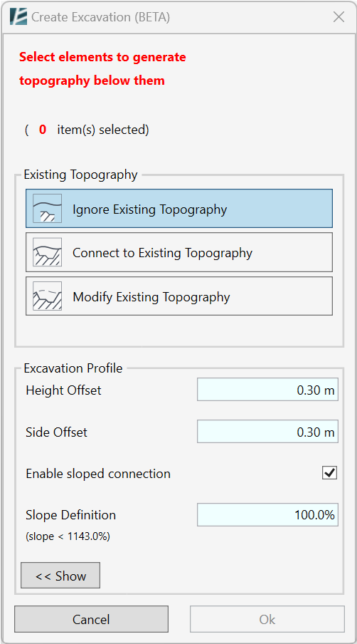
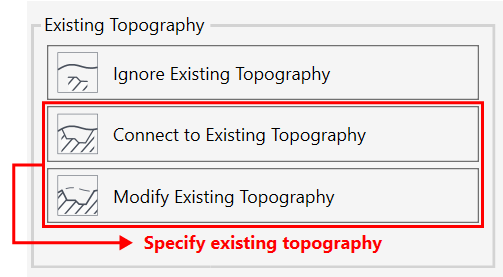
- In the Existing Topography section- select one of the three options.
This will determine how the new excavation surface will relate to the existing topography in your model. The topography defined as Existing will be marked in magenta.
*NOTE:
- Any surface can be designated as the existing surface, regardless of the project phase in which it was created.
 - Only one topography can be selected as Existing Topography.
 - To select existing topography select the second or third option, then click on the topography in your model. To deselect, click on the Ignore Existing Topography option.
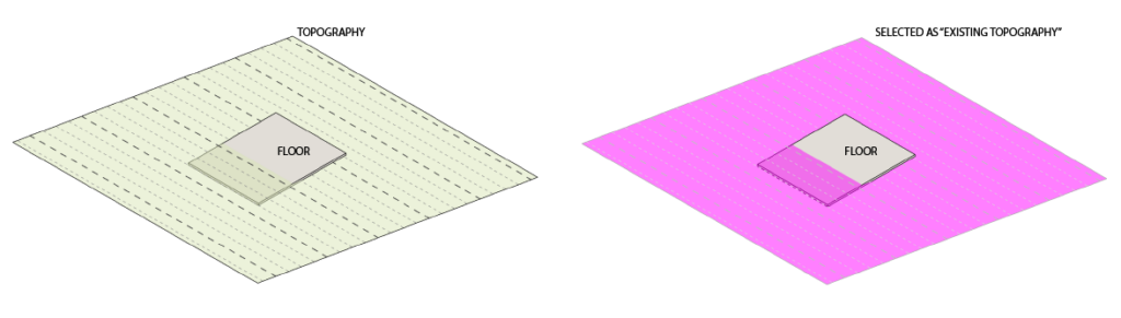
![]() 1.Ignore Existing Topography
1.Ignore Existing Topography
Creates a new topography that will only cover the area below the selected elements.
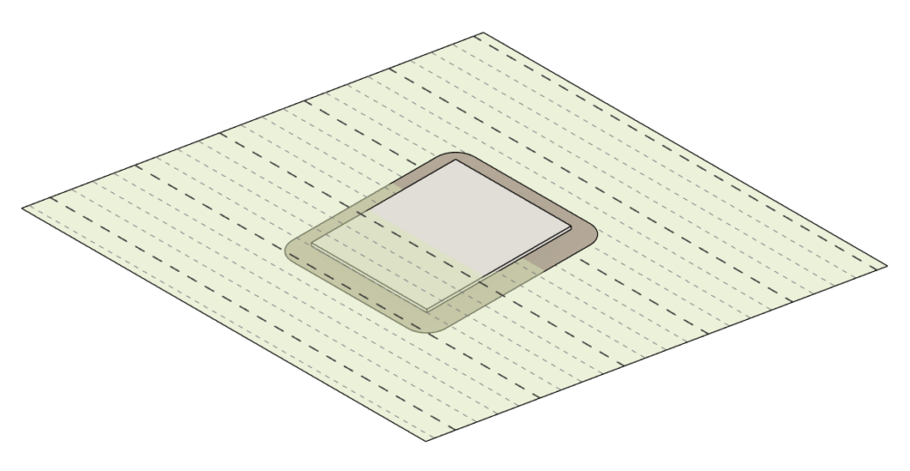
![]() 2. Connect to Existing Topography
2. Connect to Existing Topography
Creates a new topography that will cover the area below the selected elements and will also add sloped parts to connect with the existing topography.
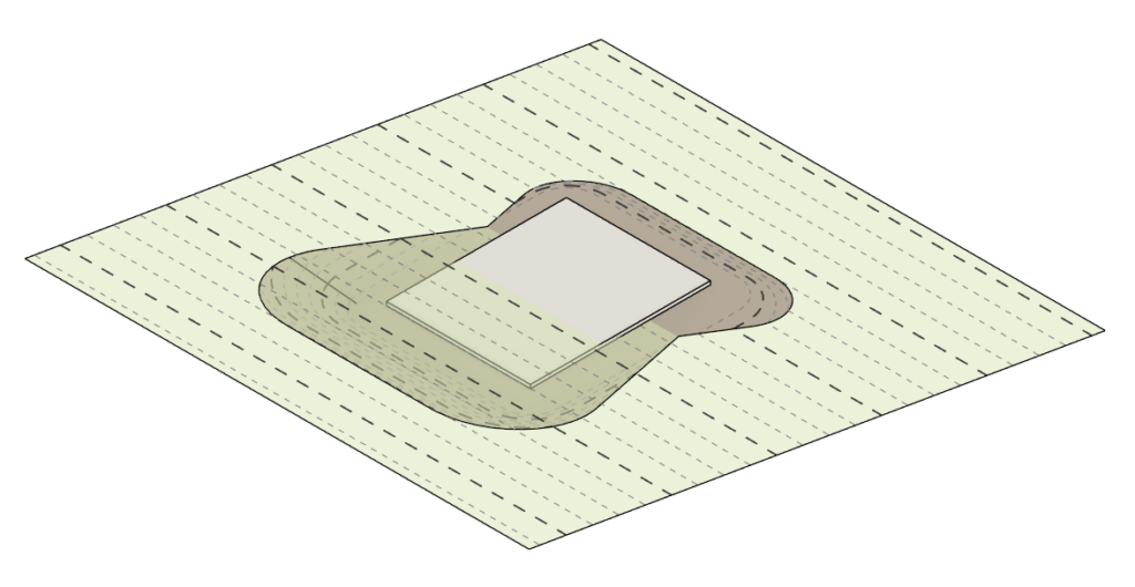
![]() 3. Modify Existing Topography
3. Modify Existing Topography
With this option, the existing topography will be modified below the selected elements, with a connecting slope.
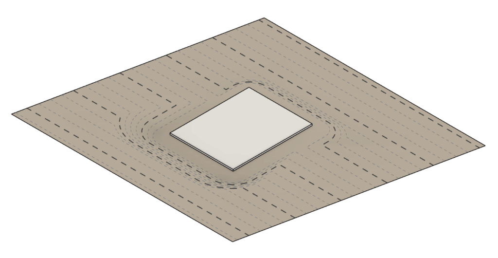
- Set the desired Excavation Profile values (Click on the “Show” button to see the diagram).
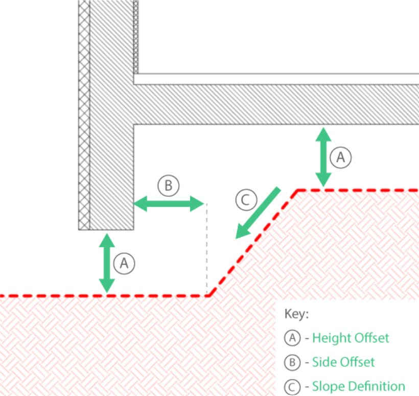
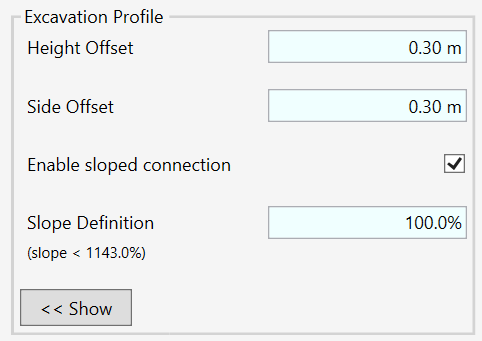
- Set the Height Offset (A) of the excavation surface from the selected elements.
- Set the Side Offset (B) of the excavation surface from the selected elements.
- Check the Enable sloped connection to connect the new excavation surface with the existing topography with a slope.
- If you enable the sloped connection, you can set the Slope Definition (C) value to define the slope percentage of the connection to the existing surface.
- Once you have configured the parameters for the excavation surface, proceed to designate the elements where the surface should be generated (This can be accomplished at any point before finalizing the command by clicking OK). You can select elements individually or with a drag-select method for multiple elements.
- Press Shift+Click To deselect elements.
- In case you have chosen to connect or modify to existing Topography, please remember to select the existing topography (marked in magenta)
- The number of selected elements will be indicated at the top of the window, shown with a green background.
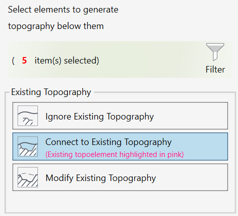
- If you selected multiple elements, use the Filter option to select elements by Category, a new window will open where you can filter by category or by level.
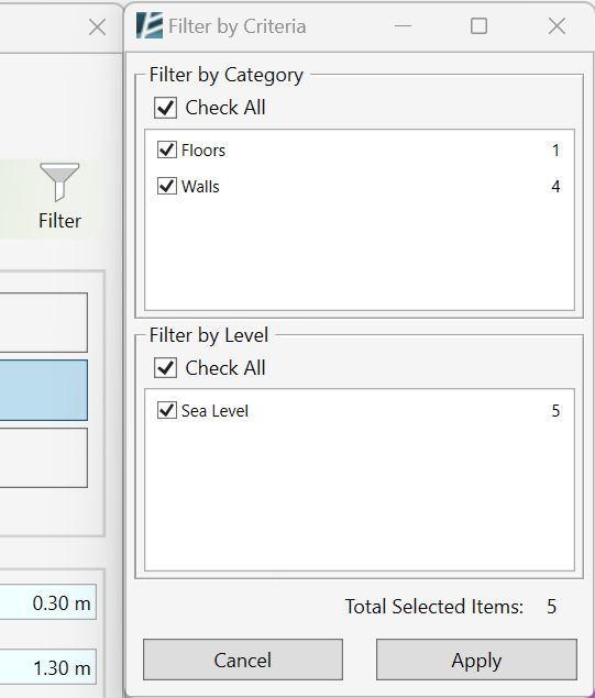
- Click Cancel to cancel and exit the command
- Click OK to complete the command.
In case you are using Revit 2024 or newer, after Clicking Ok
The GENERATE TOPOSOLID dialog box opens:
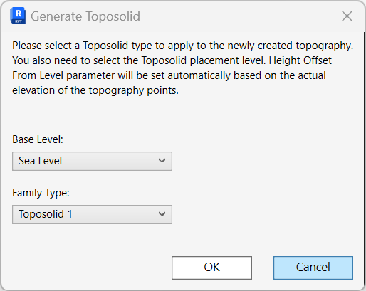
- Select the desired Base Level to be associated with the new Toposolid (the excavation surface)
- Select the desired Family Type for the new toposolid
- Click OK to continue the operation
- Click Cancel to go back to the Create Excavation Window.
Once you execute the command a progress bar window will show,
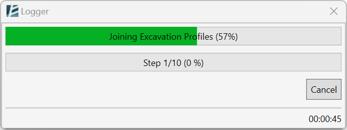
- Click on Cancel at any time to cancel the command
FLOOR TO TOPOSOLID
Create a Toposolid from any Floor in your project.
*NOTE:
- This command only works for Revit Versions 2024 or newer.
 - You can start by clicking on the command, or first select the Floors and then open the command from the Modify|Floors tab.
- Click on Environment tab > Site panel > Topography Tools drop down> Floor to Toposolid
- In the options bar- Check the Multiple box to select multiple floors
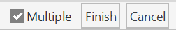
- Select the Floor(s) you want to use
- Click Finish when you are done
Or - Select the Floor(s) you want to use
- In the Modify | Floors tab click on Convert Floors Panel> Floor to Toposolid
The GENERATE TOPOSOLID dialog box opens:
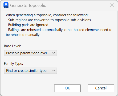
- Select Base Level for the new Toposolid
- In the Family Type drop-down, select the type of the new Toposolid.
- Click Cancel to exit the command without changes
- Click OK to finish and exit the command
You will now see the newly created Toposolid at the same location and shape as the original Floor.
*NOTE:
The original floor will not be deleted unless you manually do so.
SCAN TO MODEL
Automatically create an editable topography (Toposurface or Toposolid) from a selected Point Cloud file and use it as reference to place levels.
Before using this tool, make sure you have a Point Cloud file linked to your Revit project.
- Click on Environment tab > Interoperability > Scan to Model
- Select the point cloud
Or - Select the point cloud
- Click on Environment tab > Interoperability > Scan to Model
The SCAN TO MODEL dialog box opens:
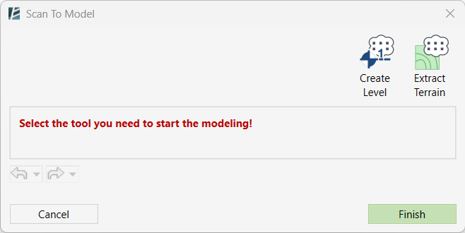
In the Scan to Model window, you have two options:
1. EXTRACT TERRAIN
Select this option to generate a topography from a Point Cloud model:
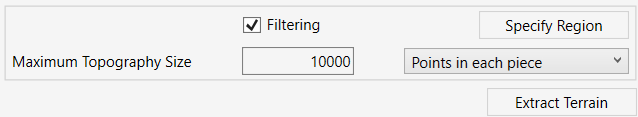
- A Section Box will appear automatically. You can adjust it to define the region from which the topography will be extracted.
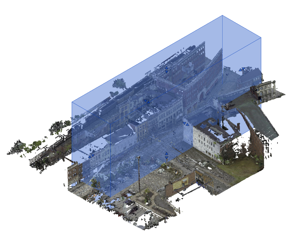
Or
- You can use the Specify Region option to sketch a free-form region of selection.
Once you are happy with the created region, click on Apply Region to confirm. - To go back to a Section Box selection, click on Reset Region.
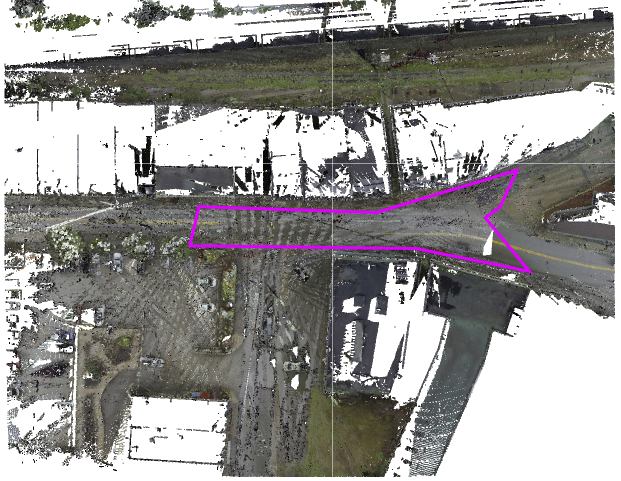
- Use the Maximum Topography Size field to control the maximum amount of elevation points within one piece of topography.
- From the dropdown menu on the right, choose how this limitation is applied:
- Points in Each Piece
The resulting topography will be divided into multiple pieces. Each piece will include up to the number of points specified above. - Points in Total
A single surface will be created, limited to the total number of points you set. This option may result in reduced accuracy compared to dividing the surface.
- Points in Each Piece
- Check the Filtering option to apply a smart filter during topography generation. Environment will attempt to ignore non-terrain elements such as trees, cars, and buildings.
If this option is unchecked, the topography will be generated using all points in the Point Cloud data, including non-terrain objects. - Click on Extract Terrain to generate the topography.
- For Revit 2024 and newer: After clicking on the ‘Create’ button, a Generate Toposolid window will open. Choose the Family Type of Toposolid and its attached Base Level from the drop-down lists.
- Depending on the size of the point cloud the command might take a while. You can cancel the operation by clicking on Cancel on the progress bar window
2. CREATE LEVEL
Use this option to generate Revit Levels from your Point Cloud model.
- Begin by sketching a 3D box in your model to select the point cloud area.
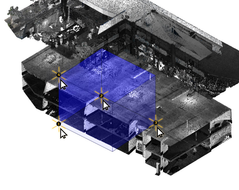
- Environment will analyze the selected volume and automatically suggest potential Levels, each with a checkbox.
- Check the checkbox next to the levels you want to import into your model.
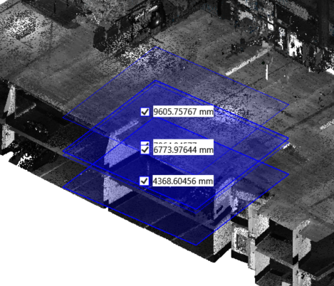
- The number of Levels selected will be shown in red.
- Choose the desired Level Type from the dropdown menu.
- In theRange Tolerance field define the vertical tolerance used to group nearby points into a single level.
- in theOffset from Range field Set the elevation offset applied to the generated Levels.
- Enable the Multiple Levels checkbox to allow the creation of more than one Level from within the defined range.
- Click Create (XX) Levels to add the selected Levels to your model.
(XX represents the number of Levels selected)
- Click Finish to complete the command.
Site Elements
ALIGN TO SURFACE
ROTATE ELEMENTS
ROCKERY ELEMENT
PLANTING FAMILY
AREA SCATTER
LINE SCATTER
PLANTING AREA
ALIGN TO SURFACE

Align elements with multiple surfaces without assigning a Host to elements.
*NOTE:
- It is possible to select multiple elements and surfaces in the same command, directly from your model or a linked Revit file, if the elements intersect with the selected surfaces.
- It is possible to align elements to many different surface categories such as floors, roofs, or topo-surfaces, as well as ramps, stairs, or even ceilings.
- If some of the surfaces or slabs selected are located on top of each other, Environment will align elements with the top surface selected.
- It is possible to pick elements from an assembly to be aligned but not from a model group.
- Click Environment tab > Site panel > Click on Align to Surface.
- Select the element or multiple elements to be aligned
or - Select the element or multiple elements to be aligned first
- Click Environment tab > Site panel > Click on Align to Surface.
- Click Finish.
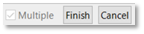
The ALIGN TO SURFACE dialog box opens:
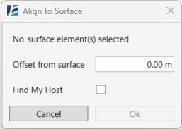
- Select a surface, a slab, or multiple alignment references and wait for Environment to process the selection.
- Insert the Offset from surface value, or leave it at 0.00 if no offset is needed.
- You can let Environment to automatically Find My Host of each element and align them to it by checking this box.
- Click Ok to apply the command
or - Click Cancel to exit the command
ROTATE ELEMENTS
Rotate selected elements in the model using a fixed or random angle.
- Click on Environment tab > Terrain and Site Components panel > Rotate Elements
- Select elements you want to rotate
Or - Select elements you want to rotate
- Click on Environment tab > Terrain and Site Components panel > Rotate Elements
The ROTATE ELEMENTS dialog box opens:
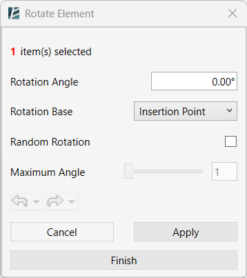
- At the top, you will notice the number of items selected.
- Type a value in the Rotation Angle field to apply a fixed rotation. Positive values rotate counterclockwise; negative values rotate clockwise.
- Choose the Rotation Base from the dropdown list. This defines the pivot point for rotation- Insertion Point or the Geometry Center
- Check the Random Rotation box to apply a random angle instead of a fixed one.
- Define the Maximum Angle to limit the random rotation range
- Click Apply to execute the rotation while keeping the dialog open.
- At any point, you can use the undo and redo buttons.
- Click Finish to apply the rotation and close the dialog,
ROCKERY ELEMENT

Automatically create rocks of different sizes (or any other site element) and place them on a host or selected level.
- Click environment tab > Site panel > Rockery Element
- On the Site Settings dialog box:
- Select the designated family.
or - Click Add to select families loaded in this project.
or - Click Browse to load families from your computer.
- Click Ok.
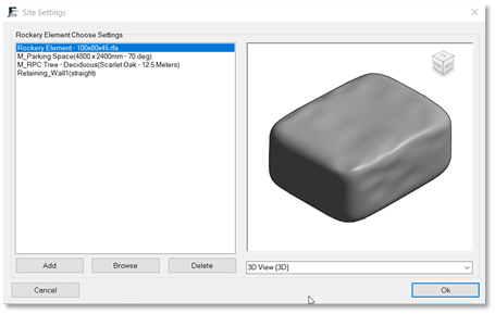
- Select the relevant level on the top ribbon.
- Click to place element.
PLANTING FAMILY
Manage all Planting Families and Plant Mixes in your project from a single interface or easily create new Planting Families and Plant Mixes from scratch. Create clear 2D and 3D representations of plants using Environment’s default geometry library or import your own geometry through the interface. Review and edit multiple type parameters manually or in bulk by importing data from an external database.
- To access the tool, click on Environment tab > Terrain and Site Component> Planting Family
The PLANTING FAMILY dialog box opens:
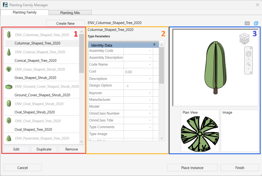
*NOTE:
- Planting Families created or edited with this tool are native Revit families. You can also edit them using Revit’s conventional tools.
- Import data from various file formats (currently: XLS, XSLX, XLSM, CSV and XML) to populate or modify your Planting Families.
The Default tab “Planting Family” contains three sections:
1. Family List:
Shows all planting Families and Types in your project. You can edit, duplicate, and remove each one of them.
2. Type Parameters:
Shows all Type Parameters for the selected Family Type. When selecting the Edit option, the parameters in the list are editable.
3. Preview Window:
Shows the graphics of the selected type in a 3D view, in a Plan View, and the associated image. When selecting the Edit option, the geometry can be edited.
Planting Families can have unique geometry for each detail level applied to a view. The preview window allows you to visualize these variations. Simply click the Detail Level or Display Style buttons at the top to cycle through different representations.
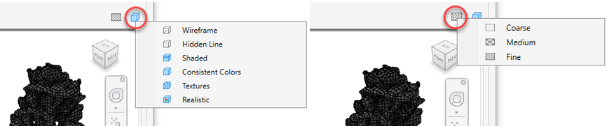
Creating a new Planting Family:
- Click Create New
The CREATE NEW PLANTING FAMILY dialog box opens:
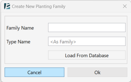
- Enter a Family Name.
- Enter a Type Name (optional). The default Type name will be the same as the Family name or you can use a type name from the database.
- Click on Load From Database (optional) to import a data file.
- Click OK to finish and go back to the main window
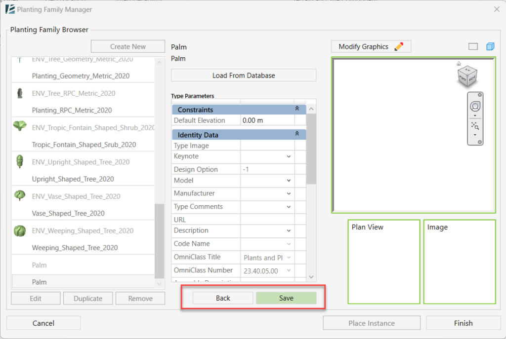
The newly created Family will appear in the Family List, and the Type Parameters will be open for editing.
- Click on Save to save the family or Back to go back without saving.
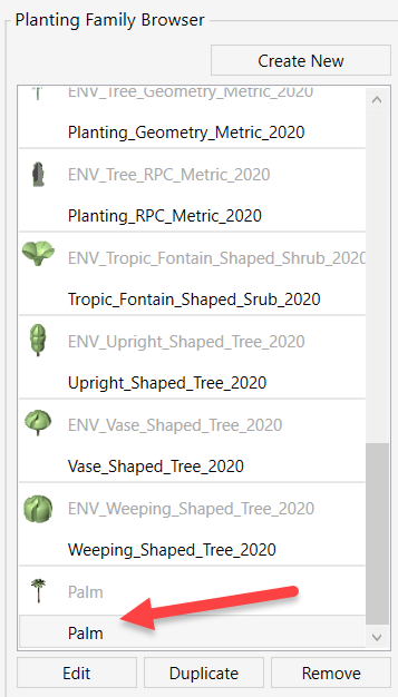
Editing a Planting Family:
- Select a Type from the list and click Edit.
In the Type Editing mode:
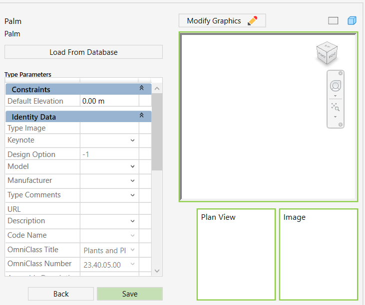
- Edit parameters manually from the Type Parameters list or import values from a database using Load From Database.
Once in editing mode, a Modify Graphics  button will be available above the Preview Window. This option provides granular control over your Planting Family’s visual representation.
*NOTE:
- In the current version of the plugin, this action will change the 3D and Plan View representation for the entire family, and the Associated Image will be applied to the specific Family Type
The MODIFY GRAPHIC REPRESENTAION dialog box opens:
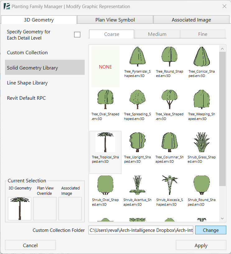
The 3D Geometry tab Lets you select the 3D geometry of your planting family.
Mark the ‘Specify Geometry for Each Detail Level’ checkbox, to enable the Coarse, Medium, and Fine tabs and select a different geometry for each detail level.
You can add a 3D geometry from one of the following 4 resources:
- Custom Collection: Build your own geometry library, by creating a local folder that contains all your planting families as (.rfa) file formats.
To set the location of the custom collection folder, click on Change at the bottom of the window and browse to set the folder path. - To extract geometries from the library, click on Add New Shape and select the Family you want to use.
- In case of complex Family files, that contain multiple types, or geometries for different detail levels, choose the Family Type and the Detail Level to specify the geometry you want to extract.
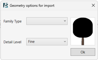
*NOTE:
- To add a new shape, you must first save your project.
- A Known limitation: If you add a Family with a Mesh geometry (for example, a family that was created from a Rhino geometry and is not a Solid) Revit cannot apply material to this shape.
- Solid Geometry Library: Environment’s default library of solid plants.
- Line Shape Library: Environment’s default library of 3D line-shaped plants.
- Revit Default RPC: Revit’s default library of RPC plants.
The Plan View Symbol tab lets you choose a 2D symbol to override the 3D geometry of the family, in a Plan View. You can also add color.
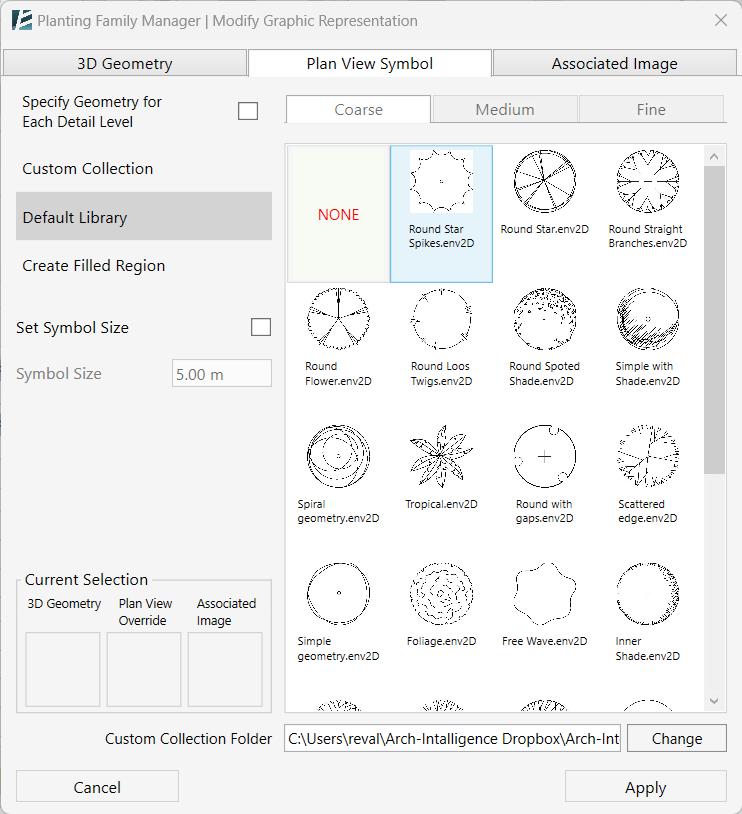
You can add a 2D symbol from one of the following 2 resources:
- Custom Collection: Build your own geometry library, by creating a local folder that contains all your planting families as (.rfa) file formats.
To set the location of the custom collection folder, click on Change at the bottom of the window and browse to set the folder path. - To extract geometries from the library, click on Add New Shape and select the Family you want to use.
- In case of complex Family files, that contain multiple types, or geometries for different detail levels, choose the Family Type and the Detail Level to specify the geometry you want to extract.
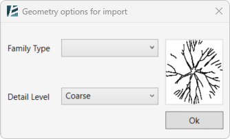
- Default Library: Environment’s library of plant geometry.
To add color to your symbol, you can add a filled region to the plan view overrides. You can combine a symbol with a Filled Region or use just one of them.
- Go to the Create Filled Region option and check the Apply Filled Region box.

- Choose the Filled Region Color by clicking on the color box. This will open the color window. Pick a color and click OK.
- To add a center mark, check the Show Center Mark checkbox.
- Select the Center Mark graphics from the drop-down menu.
- Choose the Size in Plan by typing in the value.
- For a filled Center Mark and not an outline, check the Filled Check box.
Important:
- The Planting Family tool allows you to control the size of the 2D symbol displayed in plan views. This size can represent the plant’s spread, independent of its height. To enable this functionality, simply check the “Set Symbol Size” checkbox. This creates a separate type parameter specifically for the symbol size.
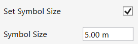
- Set the desired Symbol Size value in the textbox.
The Associated Image tab lets you add an image file to be associated with a specific Type.
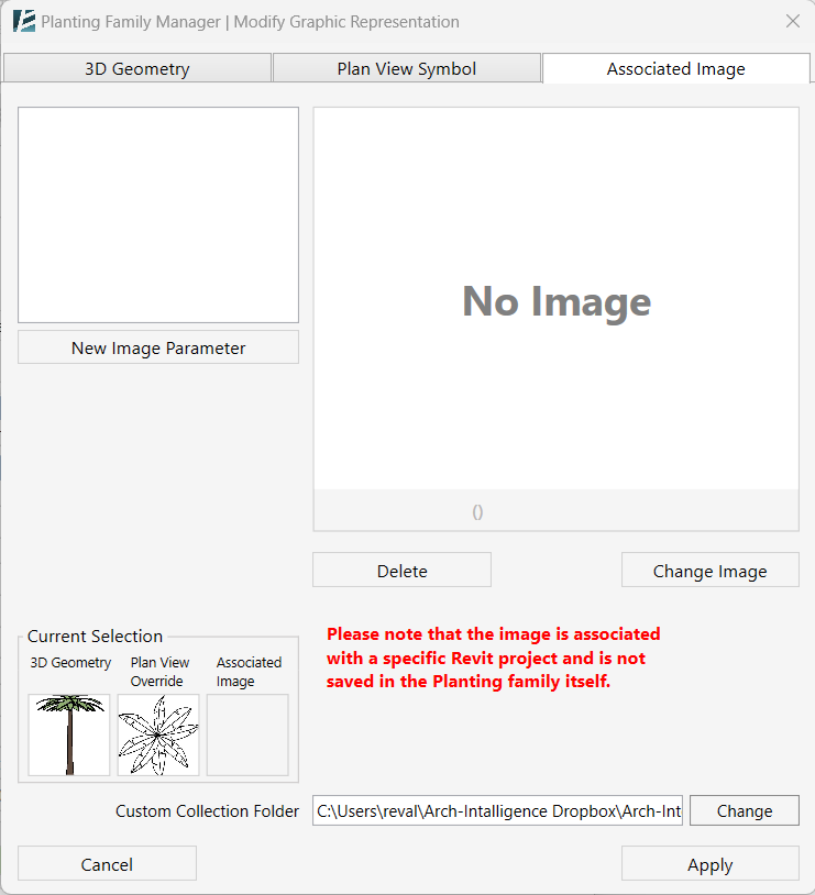
- Select a parameter from the list of image parameters
or - Click the New Image Parameter to add a new parameter.
- In the Create New Image Parameter window, add a Name of the desired parameter and click OK.
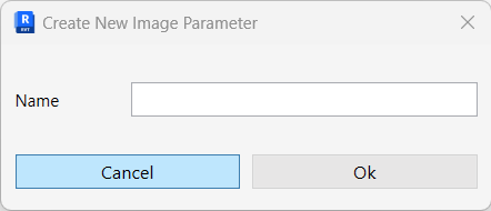
The new parameter will be added to your project.
- After selecting a parameter, click on the Change Image button to add or replace an existing image. Select an image from your local drive.
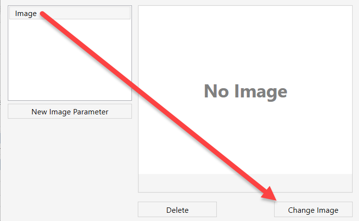
- Click on Delete to remove the image from the selected type.
Thumbnails of selected geometries will appear in the bottom left corner of the window.
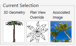
*NOTE:
- The Image is associated with a specific Revit project and is not saved in the Planting family itself.
- In case you have more than one parameter with associated images you will only see one of them in the “Current Selection” preview thumbnail.
- Click Apply to complete the process and go back to editing mode or Cancel to go back without saving your changes. Please note that the new Family is not yet saved to your project until you click on Save.
Back in the Planting Family Manager window in editing mode
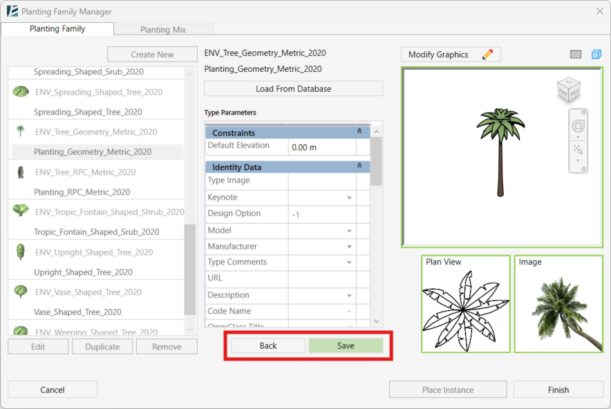
You can now click on Save under the Type Parameter list to finish editing and save the new Family, or Back to go back without saving.
- Click on Duplicate under the Family list, to copy a specific type with its properties (This will add a new type of the same family).
- Enter a Type Name or Load from Database.
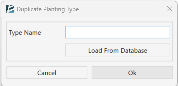
- You can delete a planting type by clicking on the Remove button under the Family list.
- The Planting Family Manager allows you to efficiently add plant instances to your model. Simply select the desired family and click the Place Instance button in the bottom right corner. You can then click anywhere in your model to place the plant. Click ESC to go back to the Planting Family Manager window.
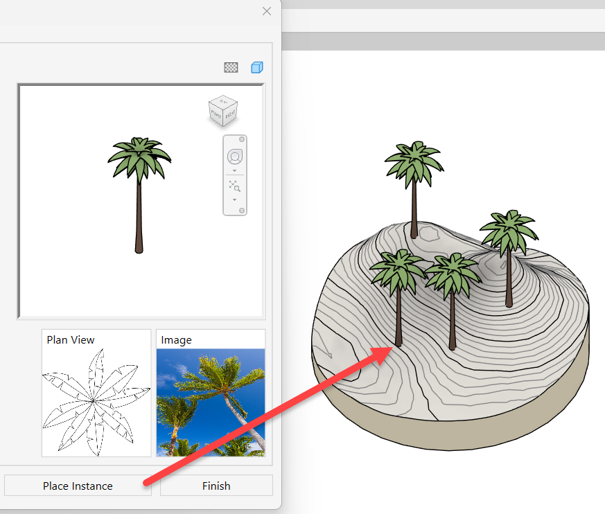
- To finish and exit the Manager click on Finish.
Importing External Data:
The Planting Family tool allows you to import parameter values from external databases (XLS, XSLX, XLSM, CSV, XML). This functionality is available when creating a new Family, editing an existing Family, or duplicating a Family Type.
Click the ‘Load From Database’ button to open the Planting Database window.
You can import several data files as your source. The ‘Data Source’ window on the left will display a list of the available imported data sources.
- Click on Add Source to browse and select a new database source file. Once selected, click Open.
Or - Choose a Data Source from the list by clicking on it.
When a data source is selected, the list will appear in the right panel, allowing you to turn each column into a Type parameter, and each row into a Family Type. Please keep in mind that in the current version, you can only create one Family at a time, with as many types as you need.
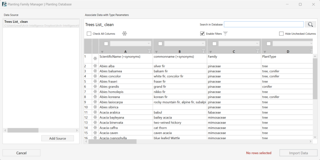
- Check the checkbox at the top of each column to add the data below as a specific Type parameter.
- To associate a parameter with the column, select one from the drop-down list (In case you checked a column but did not choose any parameter- this column would be ignored.)
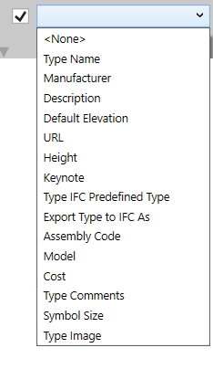
- You can hide all unchecked columns by checking the Hide Unchecked Columns checkbox.
- You can Filter the results in each column by clicking on the Funnel
 symbol at the top of each column.
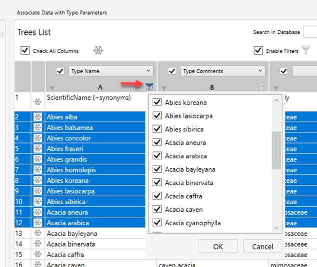
- you can disable all filters by unchecking the Enable Filters
 checkbox.
 - Enter a value to the “Search in Database” text box and click on the Search button
 to search through the database.
 - The database import window allows you to “freeze” specific rows at the top of the list. These frozen rows will remain visible regardless of filtering or sorting operations, making it easier to reference key data points. To freeze a row, simply click the Freeze button next to it. Frozen rows will be highlighted in light blue.
- To unfreeze all rows, you can click on the unfreeze button at the top

- Creating Families from Database Rows: Click on a row in the table to select a specific plant species and populate its corresponding parameters into a new family type. The selected row will be highlighted in dark blue.
- Multiple Family Creation (Optional): In Create New or Duplicate modes, you can create multiple Types from the database. Hold the Ctrl or Shift key while clicking rows to select them. The total number of selected rows will be displayed in red text at the bottom of the window. Each selected row will be transformed into a unique Family Type.
- Click on Import Data to finish the Family creation and insert the selected data or Cancel to go back to the previous window without making any changes.
PLANTING MIX:
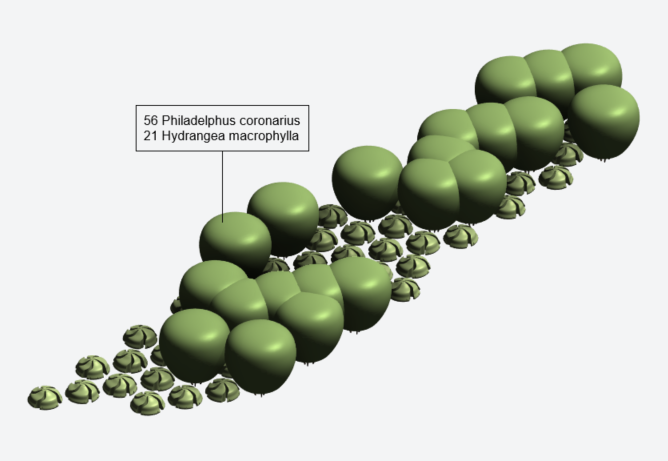
NOTE:
- A Planting Mix is a conceptual entity that stores all predefined composition, spacing, and placement settings for a group of plant species.

- Planting Mixes can be used in two different ways, depending on the desired level of representation in the model:

 1. Area-based scattering of individual plants
 A Planting Mix can be used to populate an area with actual individual Planting Types using the Area Scatter tool.

 2. Representation as a Floor or Toposolid Type
 Planting Mixes created with this tool can also be generated as Floor or Toposolid Types.
 These types include all parameters and data defined during the mix creation and can be used to represent the planting mix as a single modeled element.
 This data can be represented in a Floor/Toposolid schedule for species quantities.
 The resulting Floor or Toposolid Types can later be populated with the actual individual Planting Types using the Area Scatter tool.
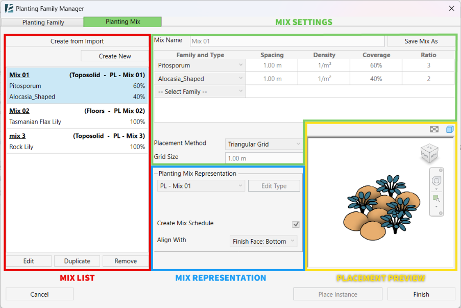
The tab “Planting Mix” contains four sections:
1. Mix List
Displays all Planting Mixes available in the project. Each mix is listed with its associated Floor (or Toposolid) Type and a breakdown of the included Planting Families and their ratios.
From this section, you can create a new mix, duplicate an existing one, edit, or remove it from the project.
2. Mix Settings
Defines the composition of the selected Planting Mix. This table allows you to assign Planting Families to the mix and control their distribution using spacing, density, coverage, ratio values and define the placement method,
3. Mix Representation
Controls how the Planting Mix behaves and is represented in the model.
This section lets you select the Planting Mix representation type, generate a mix-specific schedule, and control how the mix aligns with host elements.
4. Placement Preview Window
Displays a visual preview of the selected Planting Mix. The preview updates dynamically as you modify the Mix composition and representation settings.
- Click Create New to create a new Planting Mix from scratch.
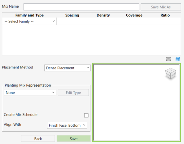
- In editing mode, Enter a Mix Name.
- Select one or more Planting Families from the drop-down menu in the Family and Type column to add them to the mix.
- Click Save to save the new Planting Mix, or Back to cancel the process without saving.
Once saved, the new Planting Mix will appear in the Planting Mix List
- Alternatively, click Duplicate to create a Mix with the same settings as an existing one, or, click Create from Import to generate a Planting Mix based on external data.
*NOTE:
- When using Create from Import, make sure the selected file is in the correct format (*.envMix). This file format can be created and saved directly from the Planting Mix interface by using Save Mix As after defining a mix.
- Select a Planting Mix from the Mix List and click Edit to edit a mix.
- Change the name of the mix by editing the Mix Name field.
- Set a species by selecting a Planting Family Type from the list.
Only Planting Family Types that already exist in the project are available for selection.
You can add as many species to the mix as needed. - Set the Spacing parameter.
This value represents the protected radius area of the plant, or the seeding distance between instances.
By default, the spacing value is derived from the selected Planting Family Type, but it can be modified manually.
When the spacing value is changed, the Density is recalculated automatically for review.
NOTE:
The Spacing parameter is only editable when Dense Placementis selected as the Placement Method.
- Set the Coverage value for each species as a percentage of the mix area.
Make sure the total coverage of all species in the mix does not exceed 100%.
The Ratio value is calculated automatically based on the defined coverage values. - Set the Placement Method from the drop-down menu.
You can choose between Dense Placement, Triangular Grid, or Rectangular Grid.- If Dense Placement is selected, you must define the Spacing value individually for each species in the mix.
- If a Grid placement method is selected (Triangular or Rectangular), define the Grid Size by editing the value.
The grid size controls the uniform distribution of planting instances across the mix area.
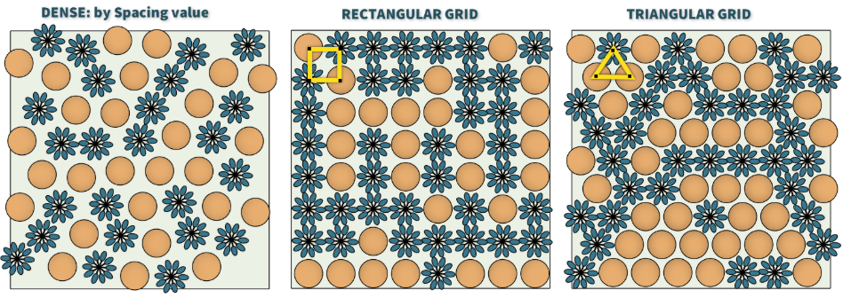
Planting Mix Representation
- In the Planting Mix Representation section, select a Floor or Toposolid Type from the drop-down menu to represent the mix in the model.
- Click Edit Type to modify the selected representation type.
From the Edit Type window, you can also duplicate the type if needed.
NOTE:
The same representation type cannot be assigned to more than one Planting Mix.
- Check the Create Mix Schedule box to automatically generate a schedule that includes all instances of the selected Planting Mix.
When enabled, a new Schedule View will be created in the project. - Select an option from the Align With drop-down menu to define which part of the Floor the Planting Mix aligns to.
- Click Save to save the Planting Mix, or Back to return without saving your changes.
AREA SCATTER
Place multiple elements in a selected area according to a set of predefined rules. The selected area can be any modeled or linked surface like Floors, Roofs, Toposurfaces, or Subregions, or an abstract area such as Areas, Rooms, Zones, or Spaces.
Area Scatter can be used to place individual family types, custom mixed combinations, or pre-defined planting mixes that were created using the Planting Mix option in the Planting Family Manager tool. This allows you to reuse the logic, ratios, and spacing definitions used in the mix consistently across projects.
*NOTE:
- While in the command, you can switch between views without exiting the command. This allows you to design freely until you reach the wanted result.

- Although this user guide may refer to plants in some examples, the Area Scatter tool is designed to work with any family and type loaded in your model.
- Click Environment tab > Site panel > Area Scatter.
The AREA SCATTER dialog box opens:
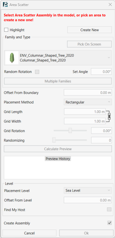
- Click Create New to create a new assembly.
- Select a host area in the model.
You can select one or more, physical or abstract area, including areas from linked models.
The selected area will be highlighted. - To deselect an area selection, click on it again.
- Click Next to start editing your scatter settings
Or
- Select an assembly in the model and click Edit Assembly to enter editing mode for an existing Scatter assembly.
- You can check the Highlight checkbox to highlight all scatter group assemblies in the model that were created using the Area Scatter tool, making them easier to identify and select.
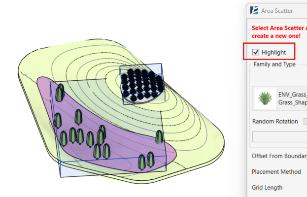
*NOTE:
- To change your selection of an area, after clicking on Applying selection, click on Edit area.
Define which Family you want to scatter in the Scatter Selection panel:
- Select a family from the drop-down menu.
or - Use the Pick On Screen option to pick any family from your model, this will automatically highlight such a family in the drop-down menu.
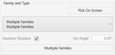
You can rotate scattered family instances after placement.
- To randomly change the placement angle of the elements, you can check the Random Rotation box
or - Enter a value in the Set Angle window to set one angle to all elements.
It is also possible to scatter multiple family types at once and create a scattered mix, either by manual selection or by using predefined scattered mixes of elements.
- To create a mix of elements, click on the Multiple Families button
In the Area Scatter | Multiple Families window:
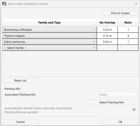
- Choose the elements to be scattered from the drop-down list or use the Pick On Screen option to select elements from your model.
- Set the relative Ratio for each element in the mix.
- If you are using the Random or Dense Method of scatter (see below), you can also set a minimum distance between each element using the No Overlap parameter (also known as Seeding or Spacing).
- Select additional elements from the drop-down list to add them to the mix. To remove an element, select – Select Family – from the list.
- Click on the Reset List button to remove all elements from the list.
When the selected host area (for example, a Floor) is already associated with a Planting Mix, the element selection options are locked.
In this case, the Associated Planting Mix field is automatically populated with the planting mix linked to that area.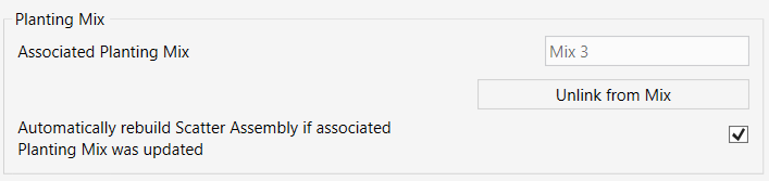
- Click Unlink from Mix to remove the existing planting mix association to manually control the scattered elements or change the planting mix.
- When no planting mix is linked to the scatter, you can click Select Planting Mix to associate an existing planting mix with the scatter.
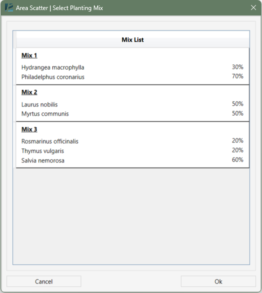
- Keep the “Automatically rebuild Scatter Assembly if associated Planting Mix was updated” checkbox checked to automatically rebuild the scatter assembly when the associated Planting Mix is updated.
NOTE:
Planting Mixes are managed using the Planting Family Manager tool. Refer to the Planting Family Manager.
- Click OK to confirm or Cancel to exit without changes.
Scatter Settings
Use the following options to control how elements are distributed within the selected area.
Enter a value in Offset from Boundary to offset the scattered elements inward from the boundary of the selected area.
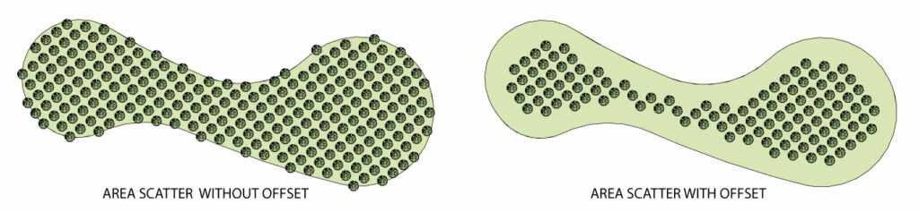
- Select a Placement Method from the drop-down list to define how elements are distributed within the selected area. Each placement method exposes a different set of parameters.
- Rectangular: Places elements on an orthogonal grid.
- Define Grid Length and Grid Width to control spacing between elements.
- Click the link icon to lock or unlock equal length and width values.
- Set the Grid Rotation angle to rotate the grid relative to the north.
- Use Randomizing to slightly displace elements from their grid positions, creating a more natural look.
- Triangular: Places elements on a triangular grid pattern.
- Define the Grid Size to control spacing between elements.
- Set the Grid Rotation angle to rotate the pattern.
- Use Randomizing to slightly displace elements from their grid positions for a more natural appearance.
- Dense: Places elements in a compact distribution.
- Define the No Overlap value to control the minimum spacing between elements.
When scattering multiple families, the No Overlap value can be defined per family in the Multiple Family window. - The Estimated Number of Elements is calculated automatically and displays the total number of placed elements.
- Random: Places elements randomly within the selected area.
- Define the Number of Elements to be scattered.
- Define the No Overlap value to control the minimum distance between elements.
- Click Calculate Preview to generate a preview of the current scatter settings without committing to a result. Each calculated preview is stored with the scatter assembly and listed in the Preview History panel.
You can select any preview from the list to review and compare different placement methods or settings before finalizing the scatter.
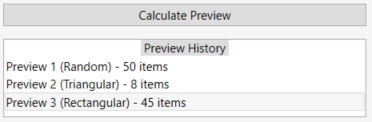
- Select a Placement Level. You can use a level from your model or use the selected area elements as a reference level by choosing the Surface Elevation option.
- Enter an Offset from level value to add height relative to the placement surface.
- If you are working with abstract areas such as Areas, Rooms, Zones, or Spaces, use the Find My Host option to find an overlapping surface and automatically host all the scattered elements on it.
Recommended: - Check the Create Assembly checkbox to create an assembly or group out of the scattered elements. This will allow you to go back and edit the scattered group later.
- Click OK to confirm your choice and exit the command or Cancel to exit the command without making any changes.
LINE SCATTER
Place multiple objects along a line or a chain of lines with multiple positioning options.
*NOTE:
- While in the command, you can switch between views without exiting the command. This allows you to design freely until you reach the wanted result.

- Although this user guide may refer to plants in some examples, the Line Scatter tool is designed to work with most loadable families and in-place families in your model.
- Click Environment tab > Area Scatter drop-down > Line Scatter
The LINE SCATTER dialog box opens:
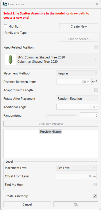
- Click Create New to create a new scatter.
- The Edit Sketch drawing tools will become available.
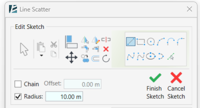
- Sketch the path you want to scatter along.
Or
- Select a scatter assembly in the model and click Edit Assembly to enter editing mode for an existing assembly.
- You can check the Highlight checkbox to highlight all scatter group assemblies in the model that were created using the Area Scatter tool, making them easier to identify and select.
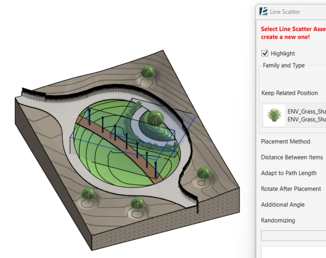
*NOTE:
- To modify the path of your selection, after clicking on Applying selection, click on Edit Sketch.
In the Family and Type panel:
- Select a family by clicking on the drop-down list and browse between the families loaded to the project. You can select any family that has been loaded into the project (except system families).
- Use the Pick on Screen option to select a type directly from the model by clicking on it.
- When the Pick on Screen option is used, the Keep Related Position feature becomes available.

Check this checkbox if you want to include the selected element in your scatter and preserve its relative position to the path.
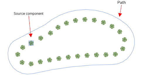
Define the Scatter Settings:
This section will only be available once you created a Scatter Path
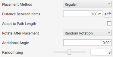
- Select a Placement Method from the drop-down list.
- Random- Use this method to create a natural effect.
- Define the Number of Elements to be placed along the path. When using this method, the distance between elements is calculated automatically.
- Regular- Use this method to place elements at a fixed interval.
- Enter a Distance Between Items value to define the exact spacing between the centers of the placed elements.
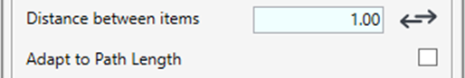
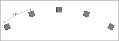
- You can use the Flip option
 to flip the direction of placement along the path
 - Check the Adapt to path Length box to distribute the elements equally along the line from start to end. Using this option the distance between the elements might slightly increase to fit the path length.
- Set the rotation method in the Rotate After Placement drop-down list.
- Use Random Rotation to randomize the rotation of the elements.
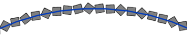
- Use Save Start Angle to place all elements using the same rotation angle as the source object.
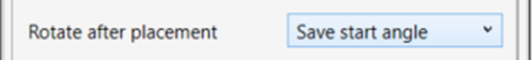
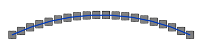
- Use Rotate With Line to align all elements relative to the path direction.
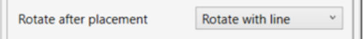
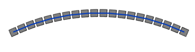
- Use Additional Angle to apply an additional rotation angle on top of the original placement angle.
- Use the Randomizing slider to introduce variation in the placement of elements along the path. Move the slider to choose a randomizing level from 1 to 6.
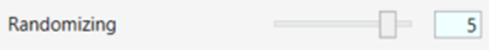
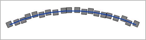
- Click Calculate Preview to generate a preview of the current scatter settings without committing to a result. Each calculated preview is stored with the scatter assembly and listed in the Preview History panel.
You can select any preview from the list to review and compare different placement methods or settings before finalizing the scatter. - Select the Placement Level to be associated with the object, from the list of existing levels in your model.
- Use the Offset from level, to assign an offset from the associated level.
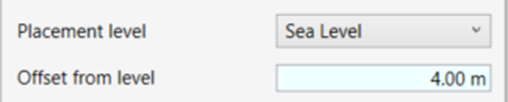
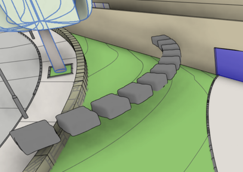
- Mark the Find My Host check box to automatically place the elements on any overlapping surface that can be used as a host.
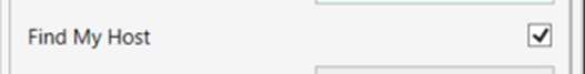
- Recommended: By checking the Create Assembly checkbox, Environment will create an assembly from all the scattered objects. This will allow you to later select and edit the assembly using the Line Scatter tool.
*NOTE:
- In some cases, an error will appear saying “Can’t create Assembly from Scatter group…” In this case, click on Combine anyway to allow creating a group or cancel to scatter the elements without combining them.
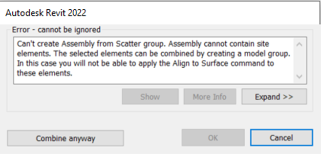
- Click on Finish Scatter to finish the process and exit the command.
- Click on Apply to see the scatter results, without leaving the command.
or - Click on Cancel to abolish all of the settings and leave the command.
PLANTING AREA
Use the Planting Area tool to place a Slab (Floor or Toposolid) that represents a Planting Mix in the model. Once created, the Planting Area slab automatically drapes on the nearest surface and takes its shape.
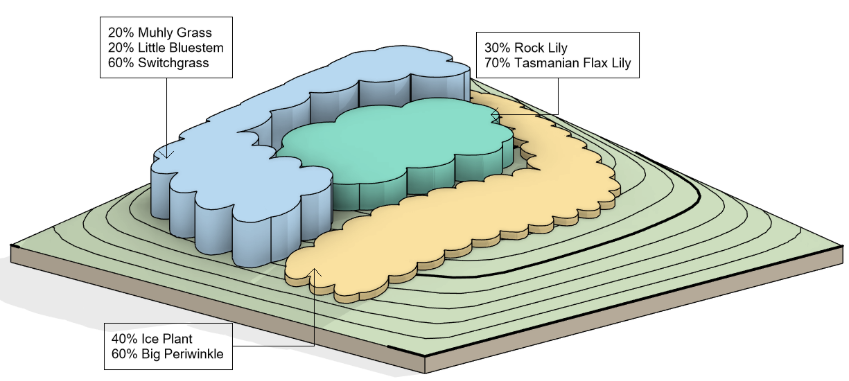
NOTE:
-This tool is available only if at least one active Planting Mix exists in the project. Create a Planting Mix using the Planting Family Manager tool and associate the mix with a Floor or a Toposolid to activate the Planting Area tool.
Click Manage Planting Mixes in the Planting Area window to open the Planting Family Manager directly.

- For scheduling purposes, the created slab contains a unique parameter that allows you to calculate the number of plants in each area according to the placement rules of the selected mix. See the Scheduling chapter for more information.
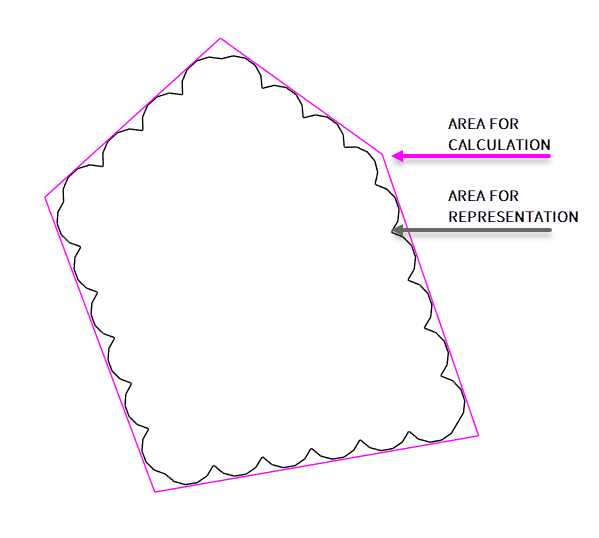
- Click Environment tab > Site and Component panel > Area Scatter drop-down > Planting Area.
The PLANTING AREA dialog box opens:
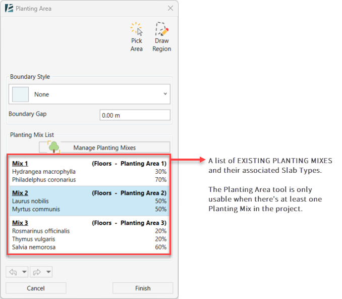
- Select the desired Boundary Style from the drop-down list:
- Select None to create a straight boundary without a predefined shape.
- Select Cloud Shape Planting Area Boundary to generate a curved boundary. The arc radius is calculated automatically based on the average plant diameter defined in the selected mix.
- Select Reverse Cloud Shape Planting Area Boundary to create an inverted cloud-shaped boundary.
- Select Planting Area Opening to create a hole inside an existing Planting Area.
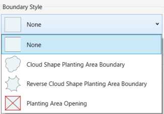
- Set the Boundary Gap value to define the offset distance between the Planting Area boundary and the selected area.
- Click Draw Region to sketch the Planting Area. The selected boundary style will be generated enclosed within the region you draw.
Or - Click Pick Area to select an existing area from the model.
Select any physical element or conceptual areas (such as Rooms or Areas) to generate a Planting Area based on their boundary.
- Use the Undo and Redo buttons throughout the command to revert or restore actions while defining the Planting Area.
Note:
- Draw Planting Areas that overlap if needed. Environment automatically splits overlapping areas to ensure that no two areas occupy the same space.
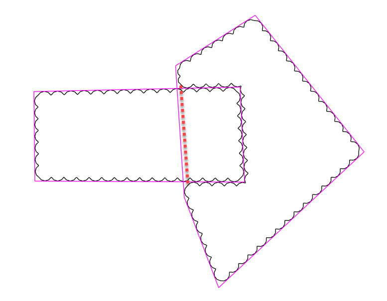
Edit an Existing Planting Area
- Select a Planting Area in the model.
- You can edit the shape of the boundary by freely moving the vertices and adjusting the lines.
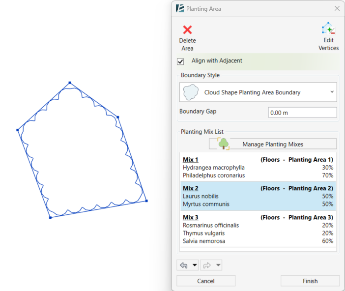
- Click Edit Vertices to add or remove boundary vertices.
- Click Delete Area to remove the selected Planting Area.
- Check Align with Adjacent to allow modifying neighboring Planting Areas together by moving common boundaries.
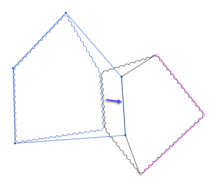
- Modify additional settings directly in the Planting Area window as required.
- Click Finish to apply the changes and complete the command. Click Cancel to exit without saving the changes.
Earthwork Calculation
CALCULATE EARTHWORK
This feature comes in the form of a Toposolid instance parameter that allows you to accurately calculate your project’s earthwork volume (also known as Net Cut/Fill).
You can then you can reliably generate estimations for all your earthwork data.
*NOTE:
- For this feature to work and calculate the Cut & Fill volume, you will need at least two overlapping topographies in different phases. For example, you can model the existing topography in the existing phase and then model several proposed topographies over the existing one, in the New Construction phase, to get the cut & fill quantities for the new topographies.

- This feature is available for Revit 2024 and newer versions only.

- This feature was developed since the native Cut and Fill parameters in Revit became unreliable after the release of Revit 2024, unless you are using the Graded Region workflow and make sure to follow its limitations (see the tutorial for more information).
IMPORTANT: In Revit 2026, Autodesk had fixed the issue, but it is still advised to use it with caution.
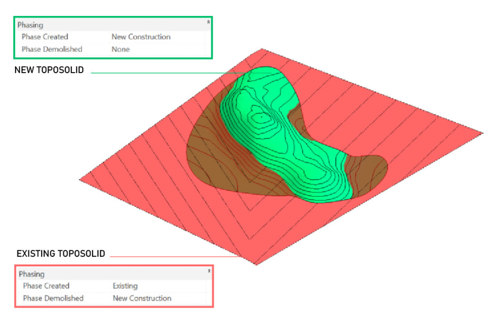
To activate the parameters for a selected topography (any Toposolid element), follow these steps:
- Select the Toposolid for which you want to perform the calculation.
- In the Toposolid properties panel, navigate to the Dimensions section.
- Check the box for the “Calculate Earthwork” parameter and click Apply.
- The new earthwork values will be displayed as follows:
- Earthwork Cut
- Earthwork Fill
- Earthwork Net (Cut/Fill)
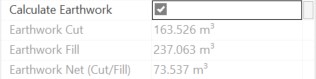
You are now free to utilize these newly created parameters as fields in a schedule.
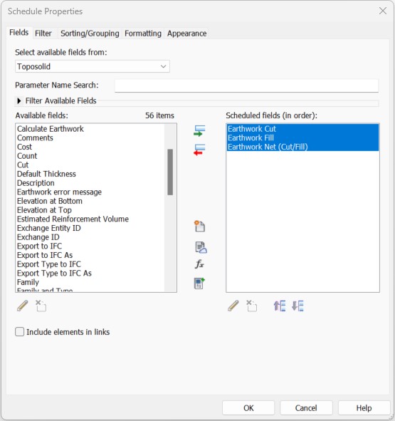
Analysis
Site Analysis
ELEVATION ANALYSIS
SLOPE ANALYSIS
ANALYSIS SCHEMES
ELEVATION ANALYSIS
Elevation Analysis creates a color-coded representation of the selected topography based on predefined elevation ranges. Each color corresponds to a specific height of interval.
Using the Material Takeoff tool, you can get an estimate of the area of each elevation range.
- Click Environment tab > Analysis panel > Click on Elevation Analysis
- Select the topography you want to analyze.
The ELEVATION ANALYSIS dialog box opens:
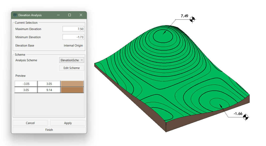
In the Current Selection box, Environment automatically detects the Minimum and Maximum elevations of the selected topography and shows the Elevation Base (the reference point for the analysis’ elevation values).
- In the Scheme box, select an Analysis Scheme from the preset options in the drop-down list.
Or - You can also edit an existing scheme or create a new one by clicking Edit Scheme.
To learn more about schemes, see the Edit Analysis Scheme tool. - Click Cancel to exit the command without making any changes
- Click Apply to confirm the changes and create the Analysis element.
- Click Finish to exit the command.
- To edit an existing analysis, open the Elevation Analysis tool and select the same topography.
NOTE:
- The analysis element includes triangulated lines that may appear visually distracting. These lines cannot be removed, but their appearance can be adjusted.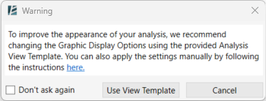
- When opening the Analysis tool for the first time, a warning message appears to recommend the use of a predefined Analysis View Template to improve the visual appearance of the analysis.
Refer to this News post to learn how to manually configure the view for a smoother and cleaner visual result. 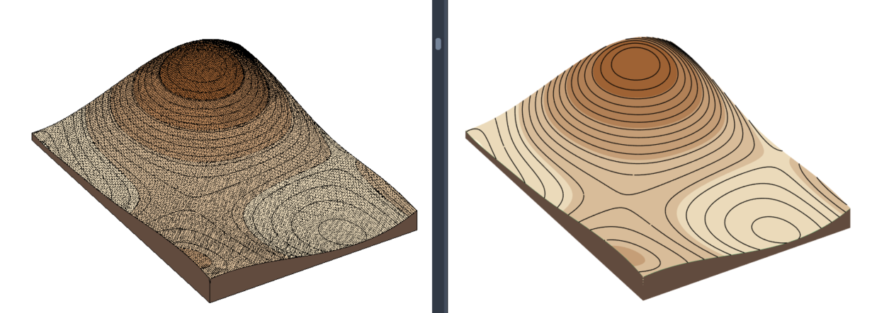
SLOPE ANALYSIS
Slope Analysis creates a color-coded representation of the selected topography based on predefined slope ranges. Each color corresponds to a specific range.
Using the Material Takeoff tool, you can get an estimate of the area of each range.
- Click Environment tab > Analysis panel > Click on Slope Analysis
- Select the topography you want to analyze.
The SLOPE ANALYSIS dialog box opens:
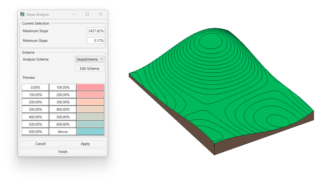
In the Current Selection box, Environment automatically detects the Minimum and Maximum Slopes.
- In the Scheme box, select an Analysis Scheme from the preset options in the drop-down list.
Or - You can also edit an existing scheme or create a new one by clicking Edit Scheme.
To learn more about schemes, see the Edit Analysis Scheme tool. - Click Cancel to exit the command without making any changes
- Click Apply to confirm the changes and create the Analysis element.
- Click Finish to exit the command.
- To edit an existing analysis, open the Slope Analysis tool and select the same topography.
NOTE:
- The analysis element includes triangulated lines that may appear visually distracting. These lines cannot be removed, but their appearance can be adjusted.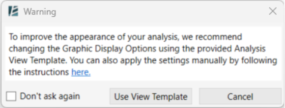
- When opening the Analysis tool for the first time, a warning message appears to recommend the use of a predefined Analysis View Template to improve the visual appearance of the analysis.
Refer to this News post to learn how to manually configure the view for a smoother and cleaner visual result.
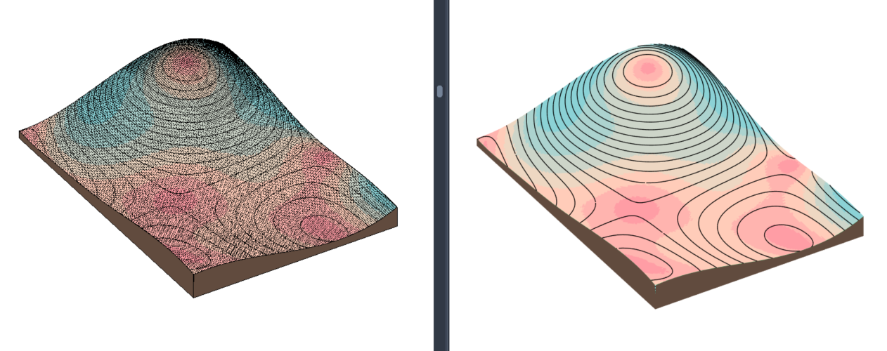
ANALYSIS SCHEMES

Create, modify, and delete schemes for the Analysis tools. It allows you to control the value ranges and the visual appearance of the resulting analysis’ visualization.
NOTE:
- The Slope Analysis tool does not support slope units in decimal degrees. When these units are used in the project, the Analysis Scheme tool will prompt you to change the slope unit (for example, percentage or ratio) before continuing.
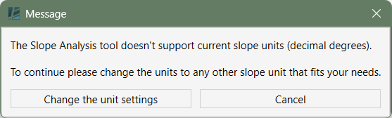
- Click Environment tab > Analysis panel > Click on Analysis Schemes
The ANALYSIS SCHEMES dialog box opens:
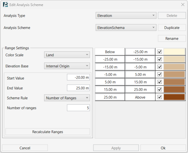
- Select the Analysis Type (Elevation or Slope) from the drop-down list.
- Select an Analysis Scheme from the drop-down list to edit an existing scheme.
- Click Delete to remove the selected scheme
(available only when more than one scheme exists for the selected analysis type). - Click Duplicate to create a new scheme based on the current settings. Enter a name for the duplicated scheme when prompted.
- Click Rename to rename the currently selected scheme.
In the Range Settings panel
- Select a Color Scale from the preset color scales.
- Select the Elevation Base to define the reference point for the analysis’ values.
- Set the Start Value and End Value to define the overall analysis range.
- Select a Scheme Rule:
- Number of Ranges – define a specific number of ranges.
- Range Intervals – divide the range using a specified interval value.
- Enter the number of ranges or the interval value, depending on the selected scheme rule.
- Click Recalculate Ranges each time you make changes and want to update the list.
In the right-hand panel
- Review the range list displayed.
- Edit the value of each range as required.
- Enable or disable a range using the checkbox.
- Click the color field to change the range color.
- Click Cancel to exit without saving.
- Click Apply to save changes and continue working.
- Click OK to save changes and exit the tool.
Representation
Datum
WALL GRID
RANGE LEGEND
RANGE LEGEND SETTINGS
WALL GRID
Automatically create grid heads that are correctly placed on wall edges, and perpendicular to the wall. You can then create a Wall Layout elevation to represent the wall’s accurate dimensions.
*NOTE:
- This command only works in plan view.
 - The first time you use this tool, a new instance parameter called "Hide In Wall Layout" is created for the Grid category. For Wall Grids, uncheck this option.
- Click Environment tab > Presentation panel > Wall Grid
- Choose the grid type from the open drop-down list.
- Click Ok.
- Place grid heads on wall edges.
*NOTE:
The grid heads are located on the wall's edges, pointing to one side of the wall. You can choose to place the grid on each side of the wall by clicking on the other side.
RANGE LEGEND

Create a color legend for the topography analysis tool to represent the analysis results.
*NOTE:
- This command automatically creates new family instances with materials used in the topography analysis and attaches Material tags to represent the different ranges.
- Click Environment tab > Analysis panel > Click on Range legend.
The SELECT RANGE LEGEND dialog box opens:
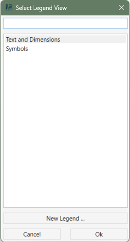
Here you will see the available legends view list. You can:
- Select an existing view to create the legend
or - Click on the New Legend… button to create a new legend view.
And then enter Name and Scale
The RANGE LEGEND dialog box opens:
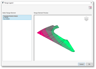
Here you can see a list of all your slope or elevation analysis.
- Select the desired analysis to create the legend from the Select Range Element list. (the selected Analysis will show up in the preview window on the right)
- Click on the Range Legend Settings
 button to modify the settings of the legend.
 - Click OK to confirm
The legend will show on the selected view including Material Tags to describe each legend entry.
RANGE LEGEND SETTINGS

Define the graphics settings of a Range Legend
The RANGE LEGEND SETTINGS dialog box opens:
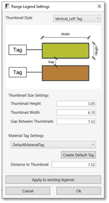
- Select the desired Thumbnail Style
- Insert a value for the thumbnail height and width
- Insert the Gap Between Thumbnails value
- Click on Create Default Tag to automatically create a designated tag family and apply it to your legend
or - Select an existing material tag from the drop-down list.
- Insert the value for Distance To Thumbnail to determine the distance of the tag from the legend.
- Click on Apply to existing legends to apply these settings to all analysis legends in your model.
- Click Ok to go back to the Range Legend window.
- From the list, select the analysis you wish to create the legend for.
- Click Ok to exit the command.
Detail Analogue
WALL LAYOUT
WALL LAYOUT SETTINGS
FAMILY THUMBNAIL
OBJECT OUTLINE
UPDATE OBJECT OUTLINE
SURFACE PROFILE
PROPERTY LINE PROJECTION
WALL LAYOUT
Create wall layout elevation to represent the true dimensions of the wall.
*NOTE:
- To create a wall layout, a single chain of connected walls must be selected.
- The wall layout is generated as an Elevation view containing Filled Regions.
The Filled Regions are created automatically and inherit the name and pattern of the wall’s type.
Lines are also generated to represent adjacent surfaces in the drawing.
- The Railing hosted on this wall is also displayed with the help of the filled region.
- Conditional lines represent the profile of the surface on both sides of the wall, and the topography related to the previous phase.
- This tool only works in a 3D view.
The resulting Elevation view will be associated with the 3D view and reflect its visible elements.
- Click Environment tab > Presentation panel > Wall Layout.
The WALL LAYOUT dialog box opens:
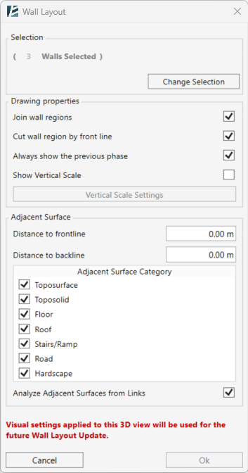
- Select a wall or several connected walls in your model.
- Click on a selected wall to deselect.
- After selecting the walls, click on Pick Face
- The number of selected walls will appear in the Selection section.
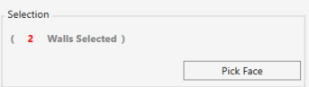
- Pick the face of one of the selected walls to define the front face for the elevation view.
- Click Change Selection to pick a different set of walls.
DRAWING PROPERTIES
- Check the Join wall regions checkbox to combine adjacent wall faces into a single Filled Region. If unchecked, each face is treated separately.
- Check the Cut wall region by front line checkbox to split the wall region at the surface level, creating separate filled regions for the above- and below-ground parts of the wall.
- Check the Always show the previous phase checkbox to display existing ground conditions in the layout, even if they are not visible in the current view.
- Check the Show Vertical Scale checkbox to add a scale on the side of the elevation.
- Click on the Vertical Scale Settings button to change the scale preferences.
The VERTICAL SCALE SETTINGS dialog box opens:
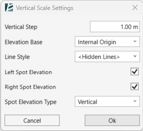
- Enter a value in the Vertical Step field to define the distance between scale marks.
- Set the Elevation Base from the drop-down menu to define the reference level for the scale.
- Choose the Line Style for the scale lines from the drop-down menu.
- Use the checkboxes to include Left Spot Elevation, Right Spot Elevation, both, or neither in the view.
- Select a Spot Elevation Type from the drop-down menu to define the style of the elevation markers.
*NOTE:
- It is recommended that the reference of the Spot Elevation matches the selected Elevation Base to ensure clean and consistent results.
- If you choose a Spot Elevation Type that does not match the Elevation Base, Environment will prompt you with a warning message
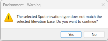
ADJACENT SURFACE
- Enter a value in the Distance fields to set the offset of the surface profile lines from the wall, separately for the front and back sides.
- Select the Category of surfaces to include in the elevation profile from the menu by checking the boxes.
- Check Analyze Adjacent Surfaces from Links to include surfaces from linked models in the wall layout.
- Click OK to confirm or Cancel to exit without changes.
Once confirmed, the drawing will appear as a new Elevation view in your project.
*NOTE:
- After making design changes to the wall, the Elevation view created using Wall Layout will not update automatically.
To reflect the changes, use the Update Wall Layout tool.
- If the wall material is changed, the Filled Region in the elevation view will be updated accordingly.
- Important: Changing elements in the elevation view will not affect the model.
UPDATE WALL LAYOUT
Update an Elevation View previously created using the Wall Layout tool.
- Open the Elevation view, created with Wall Layout tool, you wish to update.
- Click Environment tab > Presentation panel > under Wall Layout dropdown> Update Wall Layout .
The WALL LAYOUT UPDATE dialog box opens:
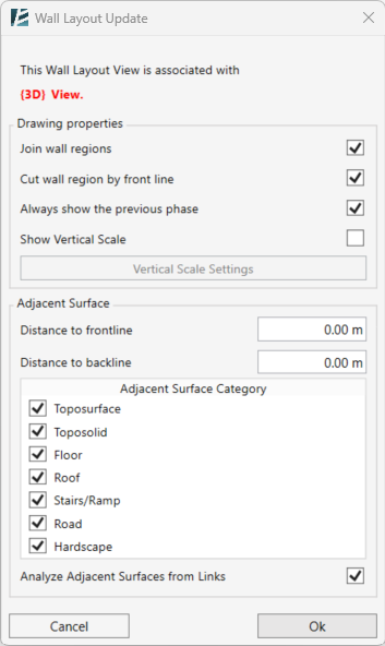
- The name of the associated 3D view will appear at the top of the window in red.
- All settings and options are identical to those set when the wall layout view was originally created and can be changed if needed.
For details on the available settings, refer to the Wall Layout user guide entry.
*NOTE:
- After updating the view, it is recommended to check that all annotations are correctly placed and visible, as the updater may occasionally misplace or hide them.
FAMILY THUMBNAIL

Create thumbnails for the families in your model and add them as images parameter in the Family Type. You can then add this parameter to your schedules to present them as legends.
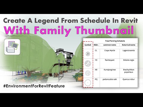
- Click on the Environment tab > Family Thumbnail
The FAMILY THUMBNAIL dialog box opens:
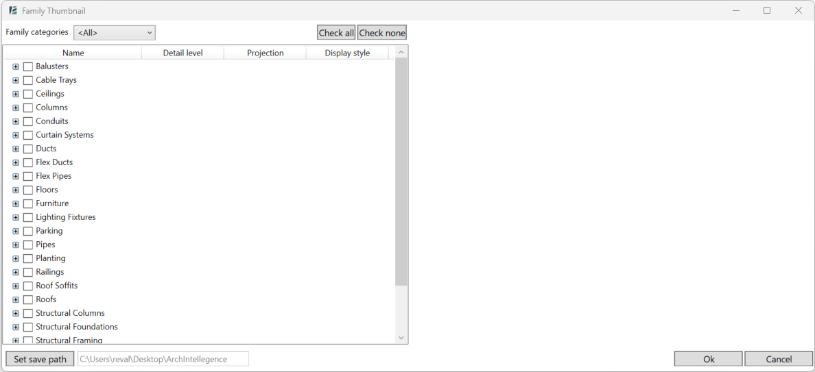
In the Family Thumbnail dialog box, you can select any families to which you want to create the Thumbnail icons. You can select an entire category, an entire family, or just a specific type:
- Use the Family Category drop-down list to filter the displayed categories.
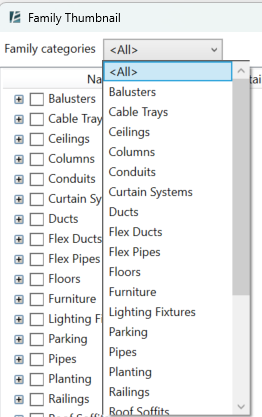
- In the left browser, mark the families which you want to create the icons from. You can select multiple types, families, and categories.
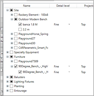
- For each category, family, or type you selected set the wanted Detail Level, View, and Style. The thumbnail will be created according to these settings.
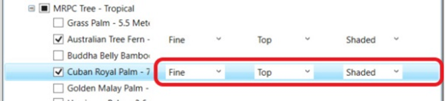
*NOTE:
You can mark a single family to see a preview of the thumbnail in the preview window.
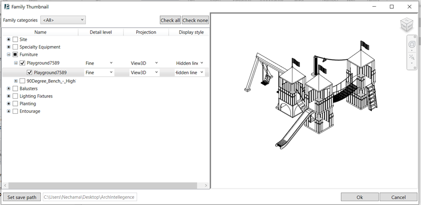
- Click “Set save path” to define the location of the thumbnail images. (These will be linked to the families they were created from).
- Click OK to finish the process.
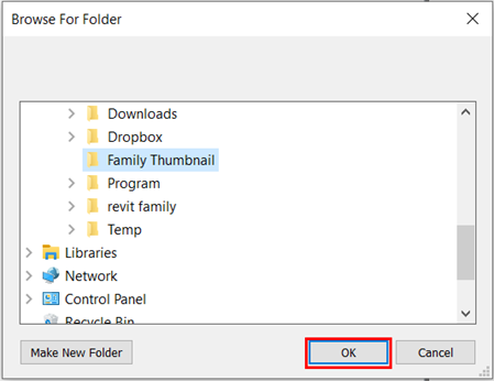
Each of the selected elements will now have a new parameter called Family Thumbnail.
Insert the thumbnails into schedules:
- Create a new schedule for the families with the Thumbnail or use an existing schedule
- Go to the schedule properties, and open the Fields tab. Add the “Family Thumbnail” parameter to the schedule
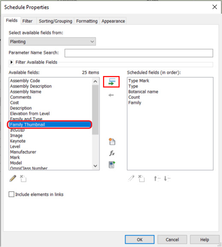
- The path to the new thumbnail will show under the Family Thumbnail column for each instance.
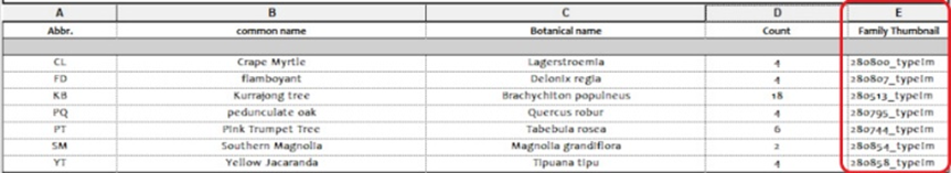
- Place the schedule on a sheet to see the created thumbnail.
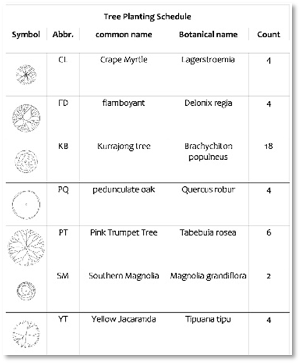
OBJECT OUTLINE

Automatically create material-matched filled regions to cover pattern deformation on sloped surfaces.
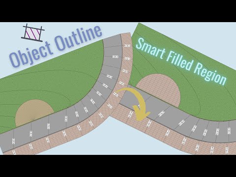
- Select the surfaces or slabs.
- Click Environment tab > presentation panel > Object Outline.
A new filled region should appear, covering the selected surface. The filled region type is created using the name of the surface’s material, and it will update with every change you make to the surface’s shape, material, or location.
*NOTE:
- If a filled region style with the same name already exists, you will see an alert and the new filled region will look like the existing type. This filled region will update once you change the attached surface.- Upon deleting the attached surface Revit will ask if you want to delete the linked filled region. - To unlink the filled region and stop it from updating with the surface, select the filled region and uncheck the Update Boundary box in the properties window. - In the filled regions type properties you can check or uncheck the box for Update Pattern.
UPDATE OBJECT OUTLINE

Update all the filled regions of the view or of the entire project
- Click Environment tab > presentation panel > drop-down arrow next to Object Outline > Update Object Outline
An alert should appear on your screen
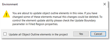
- Click Yes to apply the updates on all the current view’s Object Outline elements
or - Check the box at the bottom of the window to update all Object Outline elements in the project, then click Yes.
SURFACE PROFILE

Create a 2D representation of a surface profile in a section or elevation view. The Surface Profile command automatically creates a detail line or a spline that follows the cut topography.
- Click Environment tab > presentation panel > Surface Profile
- Select the toposurfaces.
- Click Finish in the top left corner of your window
or - Preselect the surface, and then click the command.
- Define the Line Style
- Click Ok.
A detail line appears on your drawing that updates when you edit the toposurface it is linked to.
*NOTE:
You can also create a Surface Profile for Topography that is not visible in the view. For example, the toposurface demolished in the previous phase. Preselect topography in another view, then go to your section/elevation view, and click the Surface Profile button.
PROPERTY LINE PROJECTION

Creates a detail line to represent Property Lines on a section plan or an elevation view that intersects the property line.
All Property Lines that exist on the view will be detected automatically.
*NOTE:
This command only works on section or elevation views.
- Click Environment tab > Presentation panel > Click on Property Line Projection.
The PROPERTY LINE PROJECTION LINE SETTINGS dialog box opens:
- Select a line style from the drop-down list.
- Click Ok.
New detail lines should now appear in the property line cut location.
Tree and Plants Representation
TREE CONNECTION LINE
PLANTING AREA SCHEDULE
PLANTING MIX PARAMETER
ASSEMBLY CONTENT SETTINGS
PLANTING REGION
TREE CONNECTION LINE

Connect individual Planting family items using a detail line to improve tagging and presentation of planting plans.

The created detail line will be linked to the planting families it is connecting so that changes made to them will affect the shape of the line, and respectively moving the line will cause the trees to move with it.
*NOTE:
- This command only works in Floor Plan view.
 - Connection Lines are view specific, therefore will only show in the same view they are created. Using this menu, you can edit the visibility of existing Connection Lines per view. Other editing options include adding or deleting components along these Lines and placing new Assembly Tags on any of the existing Connection assemblies.
- Click Environment tab > Presentation panel > Tree Connection Line
To open the command dialog box.
The Tree Connection Line dialog box is divided into two main tabs:
– Create Connection Line
– Place and Connect
You can mix these two options to achieve the desired result.
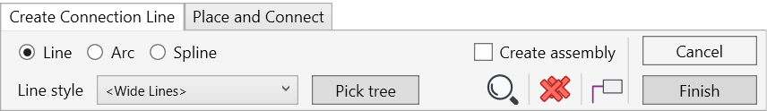
CREATE CONNECTION LINE
Use this tab to add or modify a connection line, create assemblies from planting families and tag planting assemblies that are already in your project.
*NOTE:
Connection Lines are view specific, therefore will only show in the same view they are created. Using this menu, you can edit the visibility of existing Connection Lines per view. Other editing options include adding or deleting components along these Lines and placing new Assembly Tags on any of the existing Connection assemblies.
- Choose the Line Style of the connection line from the drop-down list. This list will show all existing line styles in your project.
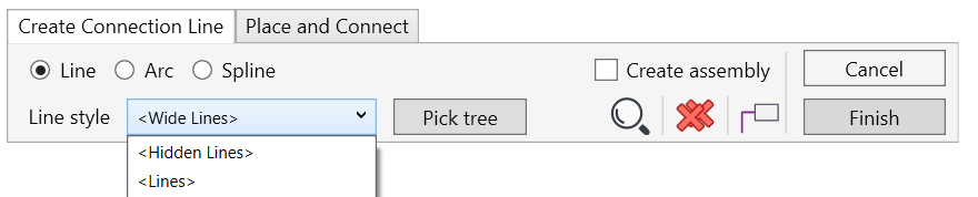
- Click on the Pick Tree button and pick the planting instances in your project to create a line connecting them.
- Click on the trees you wish to add to the connection line
- Click again on the tree(s) you wish to remove from the connection line, or to modify the connection order
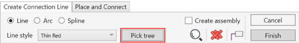
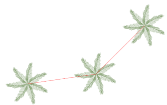
- You can swap between a straight Line, Arc, or Spline for the connection line
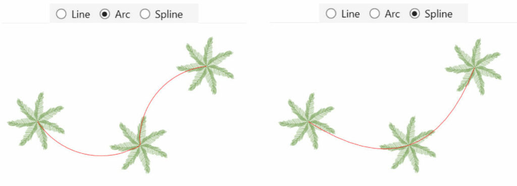
- In case you you chose the Arc options you can toggle between different shapes by clicking on the Flip Arc
 button
- If you want to be able to tag a group of connected items you will first need to turn them into an assembly. To do that automatically check the Create Assembly checkbox to add them into an assembly. Once in Assembly, you will be able to place an Assembly Tag over all the connected items.
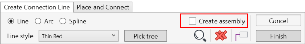
*NOTE:
Once you create an Assembly with this command, a new parameter will be created in the assembly called Assembly Content. Using this parameter, you will be able to tag and present information about every planting group created using Environment.* To set the preferences for this parameter and for the wanted assembly tag, Check Assembly Content Parameter Settings tool to set the desired tag family.
- To add an assembly tag, click on the Place Tag
 and select the assembly you wish to tag.
 - To delete all connection lines in the specific view, click on Delete all Connection in view
 , a prompt window will define how many connections are about to be deleted.
 - To add existing connection lines to a different view- go to the view you want to add the existing connections to (the trees that you want to add lines to must be visible in that view) and click on Find existing connections in this view

- the existing lines will appear in wide orange lines, and when picked they will turn into purple.
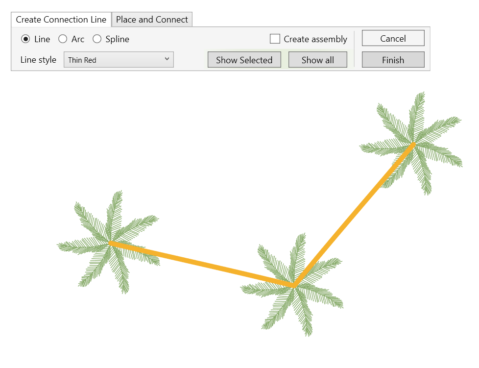
- You can choose to show the Selected Lines only- or to Show All in this view.
- Click on Finish when you are happy with the results and done.
- While in the command, you can also modify an existing connection line
- Pick the Connection line you wish to modify (Notice it would turn into a wide purple line). The new modification tools appear with a green background.
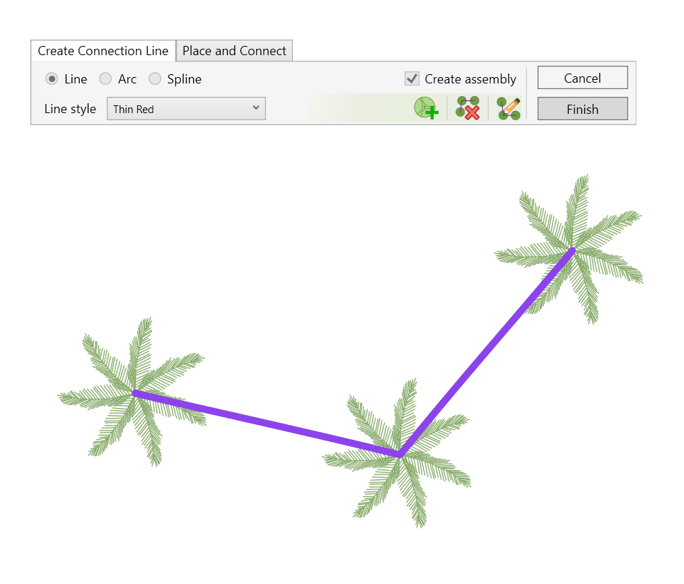
- Click on the Edit Connection Line
 to modify the line type and style, or add or remove trees from the connection
 - Click on Delete Selected
 to delete the selected line from all views. This option will also ask you whether you want to disassemble the connected elements.
 - Click on Add Tree
 to manually place and connect trees to the connection line into your model
- Click Finish to complete the process and exit the command. Or Cancel to quit the command
PLACE AND CONNECT
Use this tab to place new planting instances in your model, and draw a connection line while doing so.
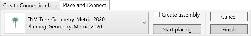
- Choose the families you want to use from the drop-down list. This list shows all planting families loaded in the project.
- Check the Create Assembly checkbox to create an assembly from the placed instances.
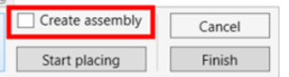
- Click on Start Placing and click anywhere in your model to place planting instances. You will see that Environment will automatically draw a connection line between the placed items.
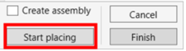
- Click Finish to complete the process and exit the command. Or Cancel to quit the command
PLANTING AREA SCHEDULE
Create a Schedule of estimated plant quantities based on the settings defined in the associated Planting Mix.
NOTE:
This tool works only if Planting Area slabs (Floor or Toposolid) have been created in the model using the Planting Area tool. If no related Slab Types exist in the project, the following message will appear:
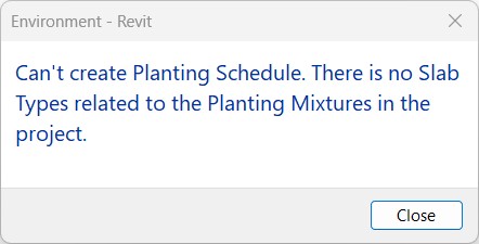
Click Environment tab > Documentation panel > Planting Area Schedule.
The Planting Mix Schedule window opens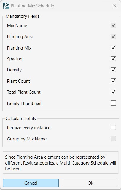
- Select the required fields from the Mandatory Fields list.
- You can check the Family Thumbnail checkbox to generate and include a preview image for each mix in the schedule.
- Check Itemize every instance to list each slab of the Planting Area separately.
- Check Group by Mix Name to group schedule rows according to the Planting Mix.
- Click Ok to create the Schedule. Click Cancel to close the window without creating a Schedule.
NOTE:
- Once the Schedule is created, the Schedule view opens automatically. Modify and further adjust the Schedule using standard Revit schedule editing tools as needed.
- Multiline parameters, such as: Planting Mix Parameter, Spacing, Density and Plant Count - are fully visible only when the schedule is placed on a sheet.
PLANTING MIX PARAMETER
Add and set the preferences for the Planting Mix Parameter (a parameter automatically created for Floors and Toposolids Planting Mixes generated using the Planting Family tool), and define the content displayed in the Planting Mix tag.
- Click Environment tab > Presentation panel> Planting Mix Parameter
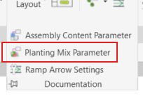
The PLANTING MIX PARAMETER dialog box opens:
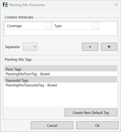
- In the Content Attributes window:
Choose what information you want to insert into the Planting Mix parameter by clicking on the three dots button next to it (the same information will be shown in the tag you place on each assembly):
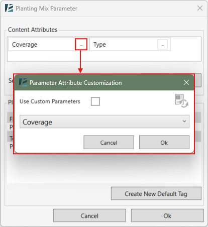
- In the Parameter Attribute Customization window, you can choose a default parameter from the drop-down menu
Or - Check the Use Custom Parameters box to add custom parameters (In this case it is recommended to update the parameter list to include the parameters of the loaded families- this can be done by clicking on the update button
 )
)
You will notice custom parameters added to the list identified by different colors and the family category they are associated with
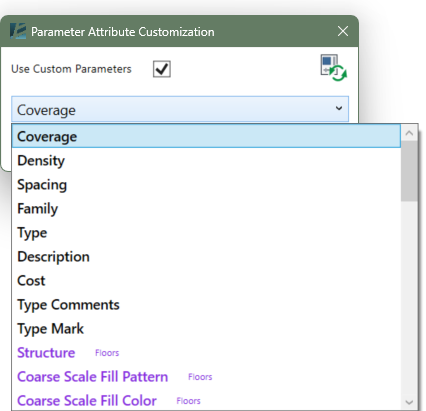
- You can add or discard parameters by clicking on the + / – buttons
- Select or create a Separator between the parameters.
TAG
To tag a Planting Mix slab, you need a dedicated Tag type. A list of these usable Planting Mix Tags in your project will appear in the middle window, separated into Floor tags and Toposolid tags.
- Click on Create New Tag to create a new tag and customize it.
- A Save New Tag window will open, allowing you to choose the tag type (Floor or Toposolid), as well as the tag name and save location.
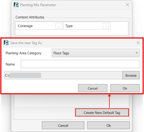
- Click OK to finish the process or Cancel to go back without creating the tag.
- Once the tag is created, it will open as a new Revit Family, where you can make adjustments and later load it into your active project. When you are done- the Planting Mix Window will show up again.
- Click OK to confirm and close the window.
ASSEMBLY CONTENT SETTINGS

Add and set the preferences for the Assembly Content Parameter (a parameter automatically created for assemblies made by Environment) and the content for the the assembly tag
- Click Environment tab > Presentation panel> Assembly Content Parameter Settings button to set the desired tag family
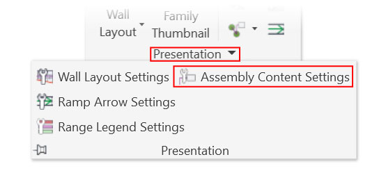
The ASSEMBLY CONTENT PARAMETER SETTINGS dialog box opens:
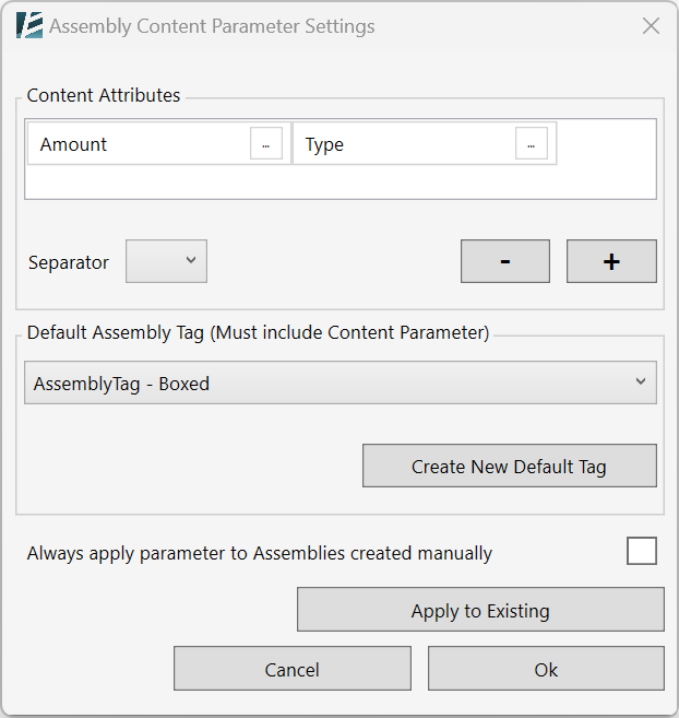
- In the Content Attributes window:
Choose what information you want to insert into the Assembly Content parameter by clicking on the three dots button next to it (the same information will be shown in the tag you place on each assembly):
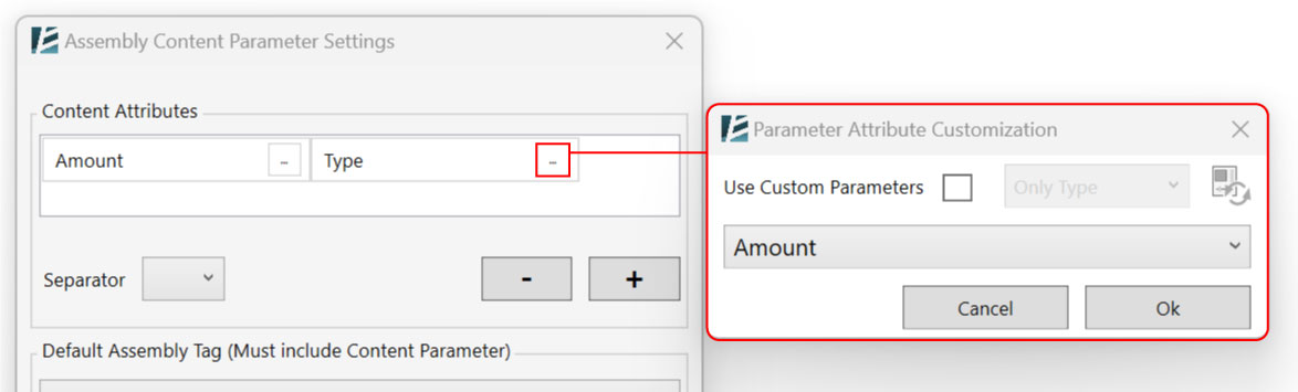
- In the Parameter Attribute Customization window, you can choose a default parameter from the drop-down menu
Or - Check the Use Custom Parameters box to add custom parameters (In this case it is recommended to update the parameter list to include the parameters of the loaded families- this can be done by clicking on the update button
 ) You will notice custom parameters added to the list identified by different colors and the family category they are associated with
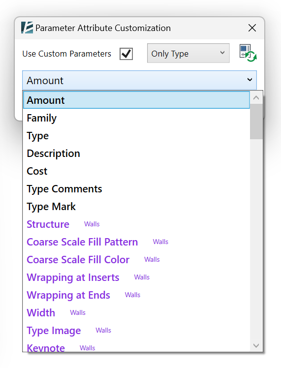
- You can add or discard parameters by clicking on the + / – bottons
- Select or create a Separator between the parameters.
- Select from the drop-down list the desired Default Assembly Tag family to be used
or, if you don’t have an appropriate tag: - Click on Create New Default Tag, to create a default tag.
- A window to Save the new Assembly Tag will open, where you can choose the name and location of the new tag.
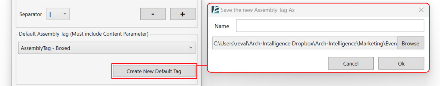
In case you have assemblies in your project that do not have the Assembly Content Parameter (i.e. assemblies that were not created with Environment) the Assemblies in the project section will show up
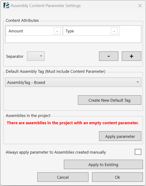
- Click on Apply parameter to add the parameter to all assemblies within your project
- You can determine to Always apply parameter to Assemblies created manually in your project by checking the box.
- To apply the Assembly Content Parameter settings to existing assemblies, click on Apply to Existing.
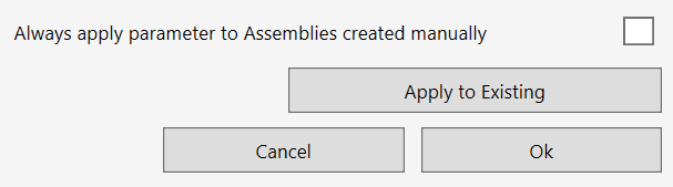
- Click Ok to finish the process and exit the window.
PLANTING REGION
Automatically create Filled Regions to cover and represent Planting elements or Planting Assemblies on any Floor Plan View in your project.

- Click environment tab > Presentation panel > Planting Region
The PLANTING REGION dialog box opens:
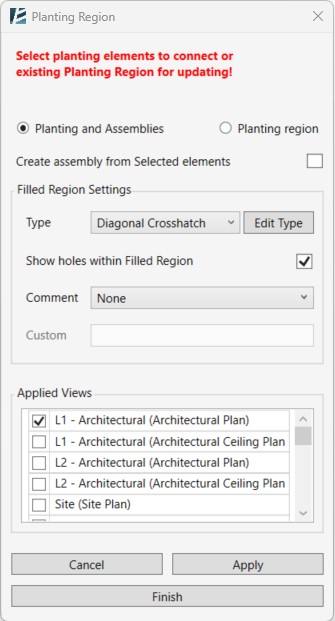
Notice the text in Red. You can either start selecting elements in your model (Planting instances or Assemblies) or you can select existing Plating Regions to update.
- Check the Planting and Assemblies option to create a new Filled Region
or - Check the Planting Region option to edit an existing Filled Region.
- When selecting several Planting instances you have the option to turn them into an assembly in the process and have the Assembly Content Parameter added to this new Planting Assembly. To do this, check the Create assembly from the Selected Elements checkbox.
- Once you select the Planting families you will notice an indication of the number of selected elements at the top of the window.
In the Filled Region Settings section:
- Define the Filled Region type you want to use by opening the Type drop-down list. The list contains all of the Filled Region types that you have in your project.
- If you want to edit a type or create a new one, click on the Edit Type button to open the Type Properties window.

- To show holes in the planting region (Fig. B) keep the Show holes within Filled Region box checked. In case you don’t want to see these holes (Fig A), Keep the box unchecked.
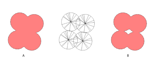
You can add a Comment parameter to each of the Filled Region instances you created. To do this, select an option from the Comment drop-down menu:
- None– to keep the comment parameter empty.
- Custom– Add custom text to the comment parameter. Choosing this option will open the Comment text window for you to manually add a comment.
- Assembly Name*– Will add the name of the assembly to the comment.
- Assembly Content Parameter*– Will add the number of elements and the name to the comment parameter (define content through the Assembly Content Parameter feature).
*NOTE:
- The last two options are only valid if you selected an Assembly (that was originally created with Environment tools) or if Create assembly from Selected elements is checked.
Under the Applied Views section, you have the option to place the same Planting Regions in more than one view in your project, by checking the desired Floor Plan Views from the list.
*NOTE:
- The Filled Region won’t update automatically if the original elements had been modified or deleted. You will have to use the Planting Region command again to modify it accordingly:
 After modifying the element(s) go to environment tab > Presentation panel > Planting Region>in the Planting Region dialoge select Planting Region> click on the Filled Region you wish to update>Back in the Planting Region dialoge click on Apply, and the planting region should update immediately.
- Click Apply to create the Filled Region without closing the window (you can keep adding more Filled Regions on the same command).
- Click Finish. To apply and exit the command.
In case you Click finish without clicking on Apply you will see this pop-up message:
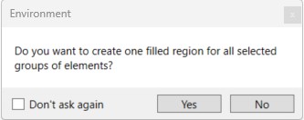
Click Yes to apply the Planting Region on the selected elements.
Ramp Arrow
RAMP ARROW
Create a run arrow on the ramp and control its appearance and location.
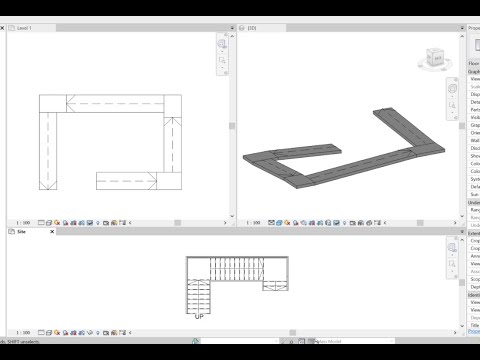
- Click Environment tab > Presentation panel > Ramp Arrow
- Click to select the ramp, or preselect the ramp and then click the command.
If this is the first time using this command in the project, a Ramp Arrow Settings dialog box opens.
RAMP ARROW SETTINGS
Define the graphics settings of a Ramp Arrow
The RAMP ARROW SETTINGS dialog box opens:
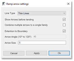
- Click Environment tab > presentation panel > the presentation drop-down arrow > Ramp Arrow Settings
- Define the Line Type for the arrows.
- Check the Show Arrows before landing box if you want arrows to appear on every run in the ramp. Uncheck it if you want an arrow to appear only on the top run of the ramp.
- Check Combine multiple arrows to a single family to set all the arrows as one element.
- Check Extension to Boundary for arrowheads to reach the boundaries of the ramp. Otherwise, define the angle and size of the arrowheads.
- Click Ok to apply only on the next ramp selection.
or - Click Apply to make changes to all ramp arrows in this project.
Workspace
Measurement
FREE MEASURE
TOTAL LENGTH
PATH LENGTH
FREE MEASURE

In 3D view, measure the distance between two points in space. Freely snap and measure the distance between two or more points located in 3D space.
- Click Environment tab > workspace panel > Free Measure
A data window appears on the top-left corner of your screen, temporarily displaying the distances and lengths measured.
To measure several distances, check the Chain box in the free measure dialog box. The continuous length between the selected points is displayed in the total distance textbox.
- Press ESC once to exit the current measurement.
- Press ESC twice to exit the Free Measure tool.
TOTAL LENGTH

Measure the length of one or more model lines.
This tool is useful when you use 2D drawings as a quick sketch in the design process and need to know the sum totals of path distances.
- Select a line or multiple lines.
- Click on environment tab > workspace panel > Total Length
The total length should now appear in a new dialog box according
to the project unit format.
- Click Ok to exit the Total Length toll.
PATH LENGTH

Measure the length of a path or projection of lines. This tool is especially useful in cases where you have a few lines above other lines, and you need to know the path length instead of the sum of the length of these lines.
- Select a line or multiple lines.
- Click on environment tab > workspace panel > the drop-down arrow on the Total length command > Path Length
The path length appears in a new dialog box displaying according to the project unit format.
- Click Ok to exit the Total Length tool.
Control
GLOBAL VIEW RANGE
NUMBER ARRAY
SELECT SIMILAR
GLOBAL VIEW RANGE

Set the view range to multiple views or view templates throughout the project simultaneously.
- Click on Environment tab > Workspace panel > Global View Range
The GLOBAL VIEW RANGE dialog box opens:
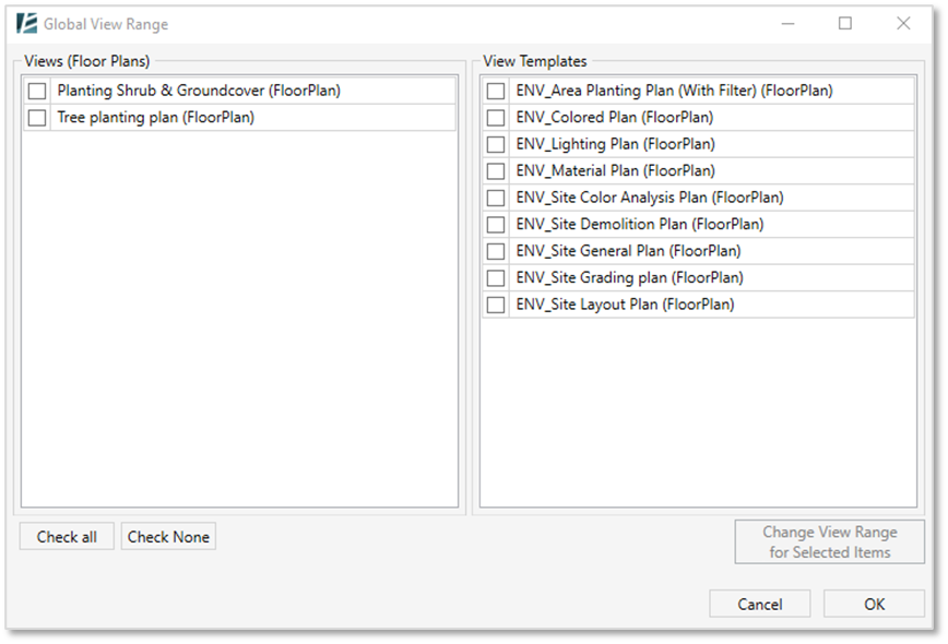
- You can check the boxes of which Views (appear in the left panel) or/and view templates (appear in the right panel) you would like to apply the new view range settings.
- You can also “Check All” or deselect all by clicking on “Check None”.
- After selecting the wanted views and view templates click on Change View Range for Selected Items
- In the View Range window, you can set the referred level and the offset value for the range of each section: Top, Cut Plane, Bottom, and the view depth.
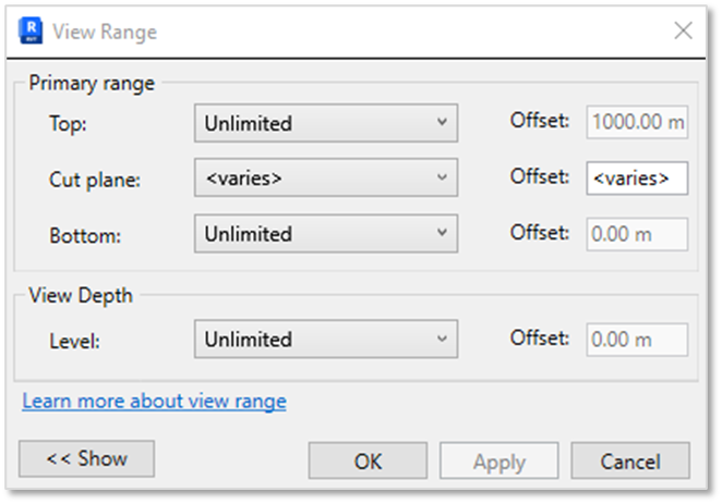
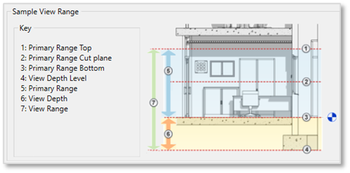
*NOTE:
Keep the levels set in order to keep the pre-set level of different views
- Click on Ok on the View Range window and click Ok again to approve the settings in the Global View Range window.
NUMBER ARRAY

Automatically number different elements in your model:
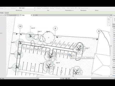
- Click environment tab > Presentation panel > Number Array
The NUMBER ARRAY dialog box opens:
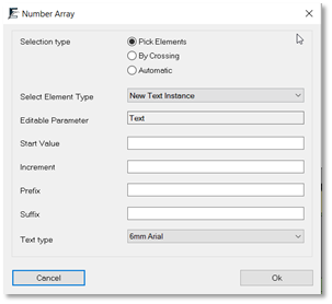
- Choose the Selection type
- Define how you want to select the elements to be numbered:
– Pick elements allows you to click each element separately.
– By crossing allows you to click Start and End to cross the designated elements.
– Automatic allows you to select an area in your model, then automatically filter only the specified family type. - Choose an Element Type from the list.
*NOTE:
- You can use New Text Instance if you want to place text numbers unrelated to any element in the model.
 - You can select an element before clicking the Number Array command, and the element type will appear selected in the dialog box.
 - You can use both numeric and alphabetic systems.
- Select an Editable Parameter:
You can edit any of the following text parameters:
– Black parameters are built-in parameters, such as Mark.
– Blue parameters are added project parameters that apply to all elements in the category.
– Cyan parameters are added project parameters that apply only to some of the selected elements in the category.
*NOTE:
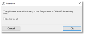
When the model already contains the specified Mark parameters, Revit asks you to delete existing parameters. Click Ok and apply the new grid heads' mark numbers. Since the Grid name cannot be deleted, Revit offers to add the “old” prefix if a specific Grid name already exists.
- Type a Start Value.
- Type an Increment value.
- Optionally, type a Prefix and Suffix.
- Select text type only when using New Text Instance on the element type.
- Click Ok.
- Select elements in the model by selection type.
- Press ESC to end the command.
SELECT SIMILAR

Use this tool to select all elements of the same family and type of your current selection.
This command also works with multiple selection sets and with other elements like toposurfaces and lines.
- Select the items
- Click on environment tab > workspace panel > Select Similar
All items of the same family and type are selected in your model.
General
License Managing
ABOUT

Manage your account and keep Environment for Revit® up to date
- Click Environment tab > About panel > About
The ABOUT dialog box opens:
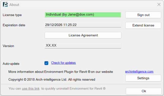
LICENSE TYPE
This section displays your licensing plan and the email address associated with your license key.
*NOTE:
Environment license is associated with an email address, but your Revit license does not have to be linked to the same address in order to use it.
You can use the license on any device you choose to within the plan limitations.
EXPIRATION DATE
Indicates when your plan expires.
EXTEND LICENSE
Click here to extend your license plan. A new window will be opened
Note: this option is not available for the corporate license types as they must be renewed via the Corporate Access Platform interface.
Click YES:
– If you have bought the license through a reseller- it will send a request to your reseller.
– If not, it will initiate the payment process for extending your license.
SIGN OUT
This button will sign you out of your license from this machine.
(In case you are signed out- you can click on SIGN IN to enter your credentials to activate the license on this machine)
VERSION
Indicates which Environment version is currently installed on your machine. It is recommended to always install the latest version since it usually includes bug fixes, feature improvements, and new features.
AUTO UPDATE
Keep this box checked to enable Environment to automatically check for the latest version every time you close Revit.
If this box is checked, in the case of a new available patch, Environment will open the following window once you close Revit:
Clicking on OK will start the update
After restarting Revit, Environment would be up to date.
*NOTE:
- For critical updates Environment will prompt with a popup window once you start Revit (even if the Auto Update box is unchecked)

- If you select to Remind me later a new button to Download New Version will show up on the Environment ribbon
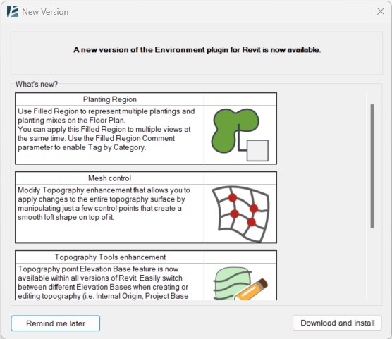
CHECK FOR UPDATES
Click this link to manually check for newer versions; this will open the download page on our website, where you can manually download the latest available version of Environment or a patch.
SETTINGS
This button will open the settings window:
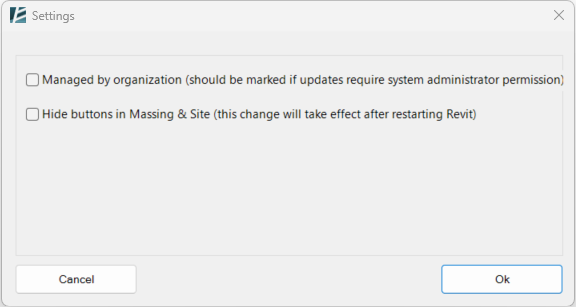
MANAGED BY ORGANISATION
Check this box if your company has an IT administrator responsible for program installations.
The end user wouldn’t be able to install or uninstall the program without the admin permission.
If checked, the “don’t show me again” option will show up
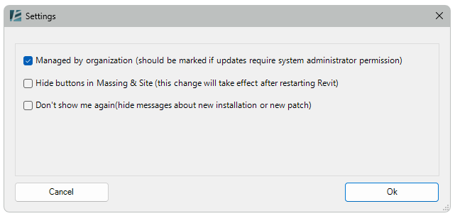
HIDE BUTTONS IN MASSING & SITE
By default, Environment adds a Panel with several tools to the native MASSING & SITE tab of Revit.
Check this box to hide this panel
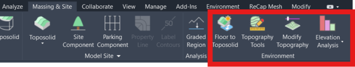
LICENSE AGREEMENT
Clicking here to see the End User License Agreement (EULA) for using Environment for Revit®.
REGISTRATION
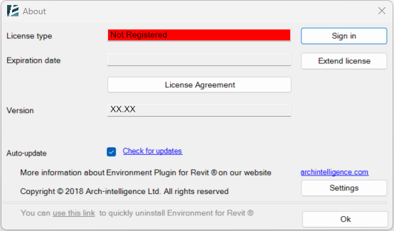
If this is your first time using the plugin
– the About window will display “Not Registered”
– click on Sign in to register
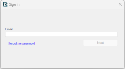
In the Sign In Window, you can insert your license credentials or retrieve a forgotten password.
I FORGOT MY PASSWORD Use this option to retrieve a forgotten Password. Once you click on this button, a new webpage is opened in your browser. Enter your registration email to retrieve your password.
EMAIL
To activate your license on a specific machine, install Environment and then enter your Email Address here. Click on NEXT to confirm and move to the next window:
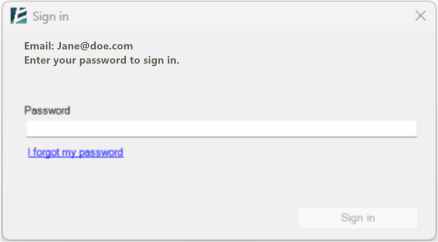
PASSWORD
To activate your license, after you enter your Email Address- Enter your password here. Click on Sign In to confirm and activate your license. If the process was successful, you will be prompted with this message:
Software Installation
INSTALLATION
To install Environment:
- Download and open the installation file provided by your reseller/Arch-Intelligence.
- Follow the on-screen instructions.
- Choose the version of Revit to install it on (only if you have multiple versions of Revit on your computer).

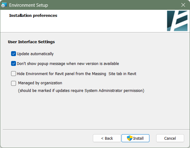
- Complete the installation and enjoy modeling.
*NOTE:
- For instructions to silent installation please visit our FAQ page
 - If you have multiple Revit versions on your computer, you can turn Environment on or off from specific Revit versions using the Environment Version Switcher. You can find it by opening the START menu in Windows and searching for “Environment version Switcher”.
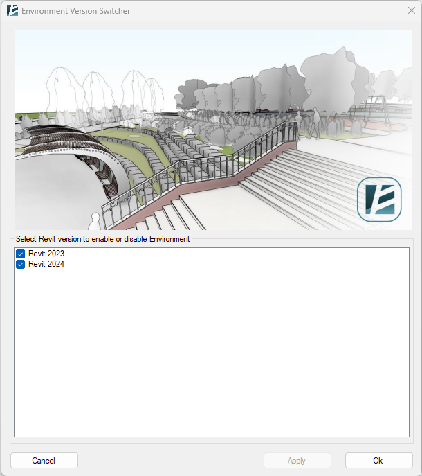
UNINSTALL
To uninstall Environment:
- You can use the Windows “Add or Remove Programs” tool
or - access the General Description window and click on the “quick uninstall…” at the bottom.
