A theoretical and practical guide on how to get it right, and why the ‘Set Coordinates’ tool was invented.
One of the main causes of confusion when it comes to Shared Coordinates, is that we often fail to geolocate our projects to begin with. And then, even when you do everything ‘by the book’, your Revit links might fall out of place for no apparent reason.
In this article, we will demystify the topic of Shared Coordinates in Revit, as well as provide the practical steps required for you to master Revit coordinates.
You will also learn how the ‘Set Coordinates’ feature can help simplify this process for you.
But first, let’s start by explaining how coordination in Revit actually works.
Note: Although written with a special emphasis on site models, the best practices mentioned here are recommended for all disciplines using Revit.
Part 1- One sea level:
While designing a building, all heights are measured based on the entrance level.
Outside of a building, however, we measure the height of each element with an ‘Absolute’ elevation, which means, the elevation above or below sea level.
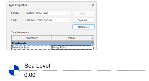
Adding an Architectural Revit level at 0 elevation, and calling it Sea Level, is the most common method of allowing you to associate elements with Sea Level, or absolute elevation, in Revit.
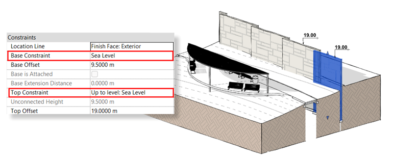
This is a must when you are building a site model since the sea level is used as a constraint for site elements such as Walls and Floors, that are not a part of a building. These elements are usually designed and tagged in absolute elevation.
It is also a must for a URS- Unique Reference System model, to keep all project teams aligned.
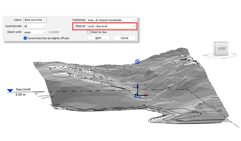
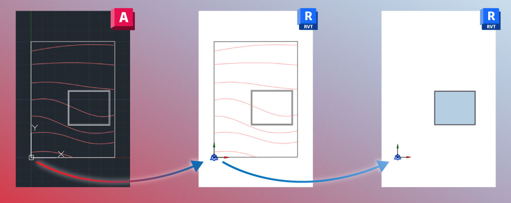
Adding the Sea Level is also essential if you want to link a CAD survey file of your site into Revit since linked CAD files should also be associated with a certain level.
Also, using a dedicated ‘Sea Level’ would make it much simpler to communicate with team members of other disciplines in the landscape design. When you name a level “Sea Level”, everyone knows what it means. In the long run, it can make it easier to monitor and solve coordination issues.
Part 2: Two coordinate systems to let you know where you are.
There is more than one way of measuring and communicating our position on earth. In Revit, we’re using two main methods of specifying our project’s location: the global system, and the local system.
So – let’s get our terminology straight.
#1: The Global System, AKA- Geographic Coordinate System or, GCS
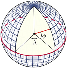
This is a well-known coordinate system, and it’s composed of geodetic grid lines wrapped around our entire globe. You probably know these horizontal and vertical lines as Latitude and Longitude. (Read more about it here: https://en.wikipedia.org/wiki/Geographic_coordinate_system )
In Revit, we use the GCS to geolocate our project, which means, letting Revit know what is our position on Earth. So that’s Geolocation in Revit.
#2: The Local Method, AKA – Datum, or a Spatial Reference System / Projected Grid
Geolocation, simply put, is how we set the address of our project, but it’s not a good way of measuring linear distances between elements in your model, since on a smaller scale we can lose accuracy.
For this reason, every country or region has its own named local datum. This datum, or local system is essentially a flat projected grid, with a defined Latitude and Longitude coordinates at its origin. Each point on the grid is defined by X and Y values and can also include a Z value to indicate the elevation from Sea Level. (Here is where you can search for local datums and compare them to the Lat and Long values: https://epsg.io/)
To make it simple, we’re using a pin to locate a chessboard on a globe. Imagine the pin is located at the board’s origin with Lat and Long values, while the chess board itself gives you the local coordinate system.
In Revit, we use the Survey Point to represent the origin of this local system.
Part 3: Three reference points to mess it all up 🤫.
So, we understand the sea level, and we know the two coordinate systems: the Global and the Local, now let’s understand how the Revit universe works.
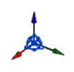
In Revit, we have 3 coordination reference points and everything in your model relates to these three points in one way or another:
First up: the Internal Origin:

The internal origin is the center of the virtual Revit universe, and it is the only reference for Revit, as a software, to understand where things are placed. This means that all mathematical calculations are done according to this point – the internal origin.
To ensure accuracy and due to mathematical limitations, your model should be more or less centered around this point. In fact, any element in your model that will be located more than 10 miles away from your Internal Origin, in each direction, may cause some serious technical issues. So, the maximum size of a Revit project is a sphere with a 20 miles diameter.
Since the Internal Origin is the center of the “universe”, it cannot be moved, so in site models, it is recommended to vertically align your IO with the Sea Level, and if your project is too far away from sea level, then you may decide to keep your Internal Origin in the project elevation.
Remember: the leading principle should be to keep your project centered around the IO.
Second: The Survey Point:

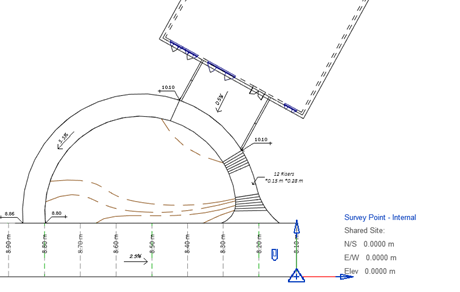
As we learned before, when we talked about the local coordinate system, the survey point is here to define our location on Earth. Once we acquire coordinates in Revit, the Survey point moves to the origin point of the local coordinate system or datum, and its X, and Y values will be 0.00.
If you want to move your survey point closer to your project, don’t forget to unclip it first, so it will move relatively to the origin of your local grid, otherwise, you will mess up the shared coordinates.
Third: the Project Base Point:

To be brief, the Project Base Point is of no importance to the geolocation or coordination of your project, and you can move it freely without affecting the project’s location.
(This wasn’t the case in earlier versions of Revit, only since version 2020.)
The Project Base Point is mainly used as a project-specific reference point and the team can decide where they want to position it. Usually, it’s placed at one of the building’s corners and vertically located at the entrance level of the building.
Part 4: What actually happens when you set the Location of your Revit model?
In Revit, we use the Shared Coordinates method to establish a common understanding of the positions and distances between elements in the model, and to ensure that all project participants share these positions. As we learned before, we can do it by speaking the common language – Geolocation and local Datum.
When we define a Shared Coordinates system, we associate our Internal Origin with a certain position on a local grid (Datum). This is what the ‘Acquire Coordinates’ feature does.
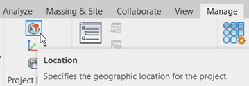
When we set the project location, we want to locate this Internal Origin on the globe and associate it with a certain address or, a Lat and Long values. This is what the ‘Location’ feature does.
This dualism can lead to some very strange situations. For example, you can have your project in the local Israeli grid, and at the same time, the location window will show the project is in Boston.
This is, in short, where most coordination issues begin:
When the local system and the global system- the geolocation – are not aligned.
To solve this, we need to align them. But in Revit, these two coordination systems are not connected by default, so the only way to geolocate your file while making sure you use a conventional local system is if you acquire coordinates from a geolocated DWG file. However, in Revit, there is no way to manually access this list of local systems and associate your file with one. Consequently, if you acquire coordinates from a simple CAD file, you’re at great risk of struggling with your coordinates later on in your project.
Part 5: The Set Coordinates feature – making collaboration easy.
To this point, we were learning how the Revit coordinate system works with the out-of-the-box tools and why we need a geolocated DWG survey file to establish Shared Coordinates in Revit. In the next part, we’ll get to know the ‘Set Coordinates’ tool by ‘Environment for Revit®’, which is a Revit plugin. This part is meant to showcase our tool, but it’s mostly a practical guide meant to help improve your Revit workflow.
Connecting the dots

At this point, you might be feeling a bit lost in the jungle of coordinate systems, and it’s safe to say we’ve all been there. This is why we added the ‘Set Coordinates’ tool to the Environment for Revit® toolset. It offers a simple way of bridging the gap between the global and the local systems while keeping an intuitive interface. This tool can help you in tons of situations, saving time and sanity throughout your projects.
So, let’s dive into 5 ways the ‘Set Coordinates’ tool can help you master Revit coordination:
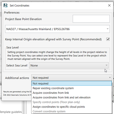
01. Set coordinates
Some projects start with no available survey data, but shared coordinates are required to collaborate with team members. Use this option, to simply enter the project address and its local Datum – and voila! You just established shared coordinates, so from now on, any data you receive will go into the right place!
02. Repair
If you’re existing Shared Coordinates are causing issues, the repair option is your savior. Just define the approximate location of your project and select the local Datum, to ensure the shared coordinates in your project are fixed! This option also allows you to adjust vertical inaccuracies, and move Revit’s Internal Origin back to elevation 0.00 – the sea level.
03. Acquire
Unsure about the geolocation of your survey data? Need an accurate URS file for your project team? The Acquire option lets you get coordinates from any linked file while ensuring your project is also geolocated. This makes it the safest option for acquiring coordinates. It worked with any linked file: CAD, Revit, or Point Cloud.
04. Convert
Sometimes you get “lucky”, and your project manager asks you to switch from one coordinate system to another. Don’t worry, the ‘Set Coordinates’ tool can seamlessly switch between datums with just a few clicks!
05. Specify Points
For surveyors who uses Revit we added the Specify Points option. Geolocate your file, select a local system, and assign coordinates by picking known points on your survey and specifying their coordinates. This can work with a PDF, a Jpg, a CAD file, or even based on a linked point cloud. You can define multiple points to get the correct angle from the true north of your project while achieving greater accuracy.
You’re welcome!
(Click here for a more detailed explanation on how to use the SET COORDINATES tool)
Whether you are an architect, a surveyor, or a BIM coordinator; starting a new project, or working on an ongoing one; a profound understanding of Revit’s shared coordinates is crucial for seamless collaboration. And with the ‘Set Coordinates’ tool by your side, you can be sure that your project will never get lost in space.
we hope this article provided more clarity and practical value to your daily work.
For more in-depth information and step-by-step tutorials, visit our YouTube channel.
Some Additional Notes:
-Useful tip: once your file is correctly geolocated, you can use it to align other files in your project by simply linking it to the other files using the ‘By Shared Coordinates’ option.
-Repair and convert might not work if some elements have restricted access when working in the cloud or when setting some constraints to elements.
-Changing the Project Base Point height while using the command will change the elevation of the levels accordingly so you should pay attention to changing the Sea Level in the process.
-Some CAD files might contain information far away in space and cause inaccuracies. These files should be cleaned using the WBLOCK command prior to inserting them into Revit.
Best practices mentioned in this article:
- Have an architectural level defined as the sea level
- keep your project centered around the Internal Origin
- vertically align your Internal Origin with the Sea Level, and if your project is too far away from sea level, then you may decide to keep your Internal Origin in the project elevation.,
- If you want to move your survey point closer to your project, don’t forget to unclip it first, so it will move relative to the 0.00 coordinate in the local datum, otherwise, you will mess up the shared coordinates.
- Make sure that the local datum matches the world geolocation (using the Set Coordinates tool or by acquiring coordinates from a geolocated DWG file)