An Arch-Intelligence team Article
Redefining the way we think and work when designing landscapes
By Oren Bar-Ner & Nehama Shechter Baraban
Building Information Modeling, or BIM. Doesn’t sound very earthshattering, does it? Anyone not in the AEC sphere would have a hard time guessing just how far reaching the impact these three nondescript words, and everything that they represent, have had on the discipline of architectural design.
The truth is that sometimes, even design professionals may not fully appreciate just how profound the BIM paradigm shift really is. This is especially true for us landscape designers, who, with the aid of tools like Environment for Revit®, have only recently been able to confidently move forward in the world of BIM.
In this article we’ll explore the BIM paradigm shift, how it’s reinventing time-consuming drafting activities and converting them to be a part of our actual design work, and how, as BIM continues to evolve, us landscape professionals who adopt it are gaining more of an edge in the industry.
Not only a tool, a philosophy
When Computer Aided Design made its first appearance, it kicked off a new era in architectural design, increasing speed, precision, and efficiency, allowing for endless advances in a wide swath of industries.
However, despite its well-earned place in the annals of architecture, CAD remained a tool in the hands of designers who continued to work much in the same way they always had. They drew, performed calculations, adjusted, and drew again until they believed they got it right. This cumbersome process, with its many and complicated calculations, left little room for creativity and flexibility.
Different than CAD, BIM prescribes a way of design thinking that is enabled by technologies, such as Revit®. The cornerstones of BIM, 3D modeling, parametric design, and collaboration pave the way for us to approach our designs in a wholly different way than we did in the past, leading to astounding, often unexpected benefits and results.
Moreover, BIM itself is morphing, offering more and more parameters, becoming increasingly elastic, and allowing for truly endless design possibilities. In a sense, BIM and design are converging, slowly becoming two sides of the same coin.
Practicing the theory
As referenced above, landscape design, as a discipline, has only lately begun to adopt BIM. The lag is due to the fact that most BIM tools weren’t designed for site works, such that many landscape firms continue to shy away from the transition to these more advanced technologies.
At Arch-Intelligence, however, we’re all about BIM for landscape architecture, and have been since our inception. Over the past 5 years, our team of expert landscape architects and software engineers have worked closely with many firms and landscape architects to comprehend what they would need and want to begin implementing BIM.
We continually integrate these requirements into Environment for Revit®, ultimately helping our partners in the landscape profession around the world to make the transition.
The result is that Environment now encompasses an abundantly rich toolset among which you will find, for example. Some of the most sophisticated and powerful tools available today for designing sloped surfaces, offering a combination of rubber-like flexibility and pinpoint accuracy.
To help illustrate the connection between these tools and the design and planning processes, and how they serve our objectives as planners, let’s consider more closely a few descriptive and significant examples.
Contour lines – From representation to revelation
Much of what we landscape professionals do revolves around shape, slope, and elevation, such as shaping land masses, determining elevations, and optimizing slopes to meet a variety of requirements. Traditionally, in CAD environments, contour lines served to help us convey such landform information onwards, and we spent inordinate amounts of time and effort conceptualizing, calculating, and drawing these lines as accurately as possible (sometimes, still falling short).
With the advent of BIM, Revit, and now, Environment for Revit, the contours of surfaces are calculated and displayed automatically, alleviating the need to meticulously draw every line. Instead, we now have the time and flexibility to use contour lines as a design tool to aid us in creating and sculpting surfaces to the desired shape and with the greatest possible precision.
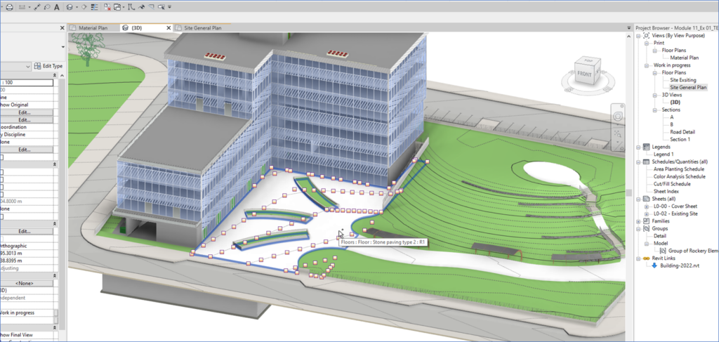
One example of this is creating perfectly shaped surfaces between or attached to other model elements. Using Revit and Environment, we can choose an anchor point along any element in our model or a linked model (one of our teammates’ models, e.g., in a linked model of a building by the architectural team), draw a contour line that passes through the point, and by doing so, design smooth, curved surfaces at exact elevations, that conform to the project constraints. We can subtract or add contour lines, or change their position, at any planning stage.
This represents an entirely new doctrine of using contour lines as anchors for purposes of modeling surfaces, in effect, to sculpt landscapes in a way that connects them to their surroundings. This, in sharp contrast to using contour lines as a “post-design” tool to express the surfaces we’ve modeled.
Expanding on this example, all we need to do is draw two contour lines in Revit, each at a different location and height, and we can use them, aided by Environment, to create a surface with all relevant data, such as slopes, elevations at each and every point along the surface, and additional, auto-generated contour lines, a surface that can be viewed in 3D, including how it connects to other model elements, a surface that we can easily check and then modify to evaluate different design options, and much more.
These contour line use cases also emphasize how the combination of Environment’s powerful toolset with Revit’s native arsenal supports the landscape architectural planning process and saves substantial amounts of time. Another good example of this is the simple, but smart annotation tool named Slope Arrow.
As indicated by its name, Slope Arrow is very simply a dynamic text element that reads in and displays the slope of any surface on which the Arrow is placed. This allows us to design and edit our surfaces as needed, while always knowing whether our slopes are correct and meet the necessary standards. Here, and in many other instances, Revit not only creates information, but makes this information accessible by providing dynamic elements that display said information.
The Revit – Environment tandem also lets us view, at any time, the final contour lines of the surfaces we model throughout the entire design process. With this, contour line information is graphically and automatically available at each planning stage, saving valuable sketching time and also helping us in our planning thinking.
Crossing to the design side – Cross Sections
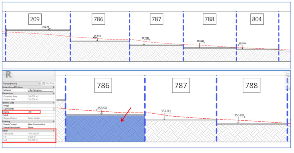
With Revit (and other BIM tools), you can create basic, but helpful Revit section views, already at the early stages of your work, allowing you to automatically and dynamically display information such as: property boundary and setback lines, lot numbers, planned elevations, and most importantly, display a cross-section of the existing terrain in a way that allows us to always know where our plan is relative to the existing site. This data regarding the relationship between our design and the existing lay of the land, is one of the most important factors influencing construction of the planned/proposed site.
In the past, similar to contour lines, we were forced to create such cross-sections manually, line after line, and updates would need to be made manually, as well, every time the plans changed. Now, with the aid of Environment’s tools, combined with Revit’s built-in capabilities, we can create print-ready section views with a few clicks. Moreover, once rendered, these sections automatically reflect shifts and changes as they are made to the model, in real-time, freeing our minds, affording us more flexibility in our design thinking, and saving rivers of time.
A final thought – BIM, design, and documentation
Before we go, here’s something else to think about: Below is an interesting excerpt from a book from the realm of documentation standards in landscape architecture and how to draft drawings. Try replacing the word “documentation” with “modeling”… Interesting, no?
“’Synergy’ generally refers to two or more entities working together to
create the greatest shared outcome. Design and documentation are not
independent activities but rather practices that depend upon one another for
mutual benefit. Documentation should be used as a design study tool and as
part of a process of exploration, evaluation, and discovery. In this way, design
benefits from thorough, wide-ranging documentation processes. Conversely,
documentation quality is enhanced with rigorous interdisciplinary design
processes. When designers work closely together, the results of that
collaboration are usually evident in the quality of documentation.”
Excerpt from: Landscape Architecture Documentation Standards – Principles, Guidelines, and Best Practices. Author – DESIGNWORKSHOP. Published by Wiley.
Conclusion
Owing to the scarcity of BIM tools for landscape architecture, it is often difficult to convey the experience of using software such as Revit to landscape design professionals. With that said, there is no doubt that the transition to BIM-oriented landscape design leads to more efficient processes, time-savings, and, on a higher level, to a different, better design experience with a broader, data-driven perspective. These provide substantial competitive advantage in today’s markets, where the BIM paradigm shift has already taken place, and all of the large players have already implemented BIM across all disciplines.