
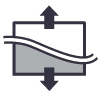
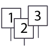
Arrange Walls
Locates and transforms walls according to reference surface.
Moves the selected walls to the intersection with the t reference surface and changes
the dimensions of the walls in accordance with the specified parameters.
Splits the wall to create the steps parallel to reference surface.
Stretch Walls
Modify the height of chosen walls.
Modifies the base/top offset value for multiple walls
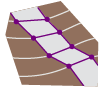
Shape Floor by Topography
Shape the floor according to toposurface.
Placing a floor sub elements in alignment to topography points.

Complete Floor
Create a new floor from an opening or hole (outlined by floor boundary or cut with a void element)
The new floor will be built at the selected level and will shape according to the original floor’s slopes.

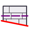
Match Slope
Slope a Floor or a Roof according to a designated, parallel slab slope.
For example, use this tool to shape a floor by a linked slab.
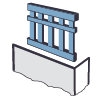
Wall railing
Create railings hosted on the selected walls.
The railing is located along the wall centerline of the selected wall.
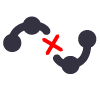
Select dependent railings
Select (highlight) all railings hosted on the selected objects.
Railing is selected along with the hosts, so first select the desired hosts, then specify
your choice using the filter.

Flip Railings
Flip multiple railings at a time. For example, when you need to switch the side of the handrail.
To easily select multiple railings use the select railings command.

Paste Curb
Create curb element using railing, by picking edges of floor or roof.
You can turn InBound mode on for creating opening and shifting your curb inside the slab.
The used railing type cannot contain Balusters, Top rail or Handrails. The profile which is used for the curb must be entirely on the one side from insertion point (left or right).

Check Elevation
Display the elevation of selected Model Lines.
A text note displaying the elevation is inserted above the selected Model Line and will be
automatically updated when the elevation of this line changes.
You can also change the elevation of the Model Line by changing the value of the
corresponding text note.

Check Elevation by Crossing
Display the elevation of selected Model Lines at the intersection with auxiliary reference
plane.
A text note displaying the elevation is inserted above the selected Model Line and will be
automatically updated when the elevation of this line changes.
You can also change the elevation of the Model Line by changing the value of the
corresponding text note.

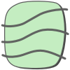
Floor Contours
Create horizontal contours on selected floors.
The ability to adjust the increment of contour lines and the used line style for each floor
separately.
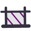
Split Spline
Split the model and detail splines.
This tool does not work with splines in the sketch mode.
Set Elevation
Lift the selected Model Lines to the Elevation value.
After lifting, the Model Line gets temporary color override.

Set Elevation by Crossing
Lift the Model Line that intersects the auxiliary reference plane to the Elevation value.
After lifting, the Model Line gets temporary color override.

Get Blocks
Use CAD link blocks to place family instances in the correct location and elevation for your project. This tool works with DWG or DXF format links.
You can place blocks by the elevation value from the CAD file or place instances on a selected level. After placing them, you can rotate all family instances according to the block rotation value in the linked CAD file.

Locate Objects
Insert family instances in coordinates from the CSV file.
For proper operation, make sure that the CSV file and the project have the same
coordinate system.

Surface from File
Create Toposurface containing points in coordinates from the CSV file.
For proper operation, make sure that the CSV file and the project have the same
coordinate system.

Export to LandXML
Export the toposurfaces to a LandXML file for better collaboration with Civil 3D or other
engineering software.
You can use shared coordinates or internal project coordinates when exporting.

Elevation Analysis
Create a color representation of the selected Toposurface’s elevations according to the preset coloring rules for every topography elevation range.
You can use the Material Takeoff tool to calculate the area of each range.
Slope Analysis
Create a color representation of the selected Toposurface’s slops according to the preset coloring rules for every topography slope range.
You can use the Material Takeoff tool to calculate the area of each range.
Create Surface
Create a toposurface from selected Model Lines.
Before creating the surface, make sure that the selected lines have an elevation.
Add to Surface
Add the selected Model Lines to an existing surface.
Insertion lines must not exceed the boundaries of selected surface.

Surface from Edge
Create a Toposurface by selecting the corresponding edges of a 3D solid objects or other Toposurfaces. Double-clicking on the edge cancels the selection.
This may be necessary when filling in the empty space between several separate elements include links. As well as creating topography in the floor opening.
Area Scatter
Place multiple elements in a selected area based on a set of predefined scatter rules.
You can select an area in your model or on a linked model. Define the scatter area using Area elements, Rooms, Zones, Spaces, Floors, Roofs, Toposurfaces, or Subregions.
Align to Surface
Align multiple elements according to the elevation of multiple surfaces without setting Host for them.
You can choose floors, roofs or toposurfaces, as well as ramps, stairs or even ceilings as a surface to align to. These surfaces can be selected right in the model and also in the Revit® link.
Rockery Element
Insert a family instance of the Rockery Element.
Bring some default Rockery Element types to the project, or load your own type.
Number Array
Numbering selected items by changing the corresponding parameter.
You can also insert a text note containing a number.

Wall Grid
Places the Wall Grid instance on the floor plan view.
The grid will be created normal to the wall face.
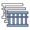
Wall Layout
Representation of the Wall Profile in expanded form.
First select the wall chain, then pick the side of specific wall for indicating the right
direction of representation. Works in the 3D view only.
Object Outline
Create a Filled Region for graphical representation of selected Floor and Toposurface
on the floor plan.
The name of this Filled Region is the same name as the selected Floor family type
name or Toposurface material name.

Surface Profile
Create a detailed representation of toposurface on secant plane.
Use this tool to show the topography of a previous phase on section view.

Ramp Arrow
Create the three dimensional ramp arrow to annotate the slope direction of the selected
ramp.
Each arrow is saved in the project as a separate generic annotation family and will be
displayed in the project browser.
Range Legend
Create a color legend for the topography analysis tool to represent the analysis result.
This command automatically creates new family instances with materials used in the topography analysis and attaches Material tags to represent the different ranges.

Property Line Projection
Creates a detail line to represent Property Lines on a section plan or an elevation view that intersects the property line.
All Property Lines that exist on the view will be detected automatically.
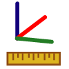
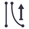
Free Measure
Measure the distance between two points in three-dimensional space.
The function temporarily displays on the screen the value of the smallest distance
between these points, the vertical and horizontal distance, as well as the total length of
the route.
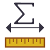
Total Length
Temporarily displays the length of all selected lines.
This includes also the length of the arcs and splines.
Path Length
Temporarily displays the length of the trajectory for all selected lines.
If the path of several lines coincide, the length of the common path of all relevant lines
will be displayed.

Select Similar
Select all similar items of selected element.
This also works with toposurfaces and lines as well as multiple selection set.